Artificial facet joint device having a compression spring

a compression spring and facet joint technology, applied in the field of artificial facet joint devices having compression springs, can solve the problems of limited motion and severe limitations in the rotation of the spin

Active Publication Date: 2006-06-15
DEPUY SPINE INC (US)
View PDF15 Cites 297 Cited by
  • Summary
  • Abstract
  • Description
  • Claims
  • Application Information

AI Technical Summary

Benefits of technology

[0031] d) a second compression resistance

Problems solved by technology

The device also allows some lateral bending motion, but ultimately limits the motion as one of the outside springs is loaded.
Finally, the ro

Method used


Image

  • Artificial facet joint device having a compression spring
  • Artificial facet joint device having a compression spring
  • Artificial facet joint device having a compression spring

Examples


Embodiment Construction

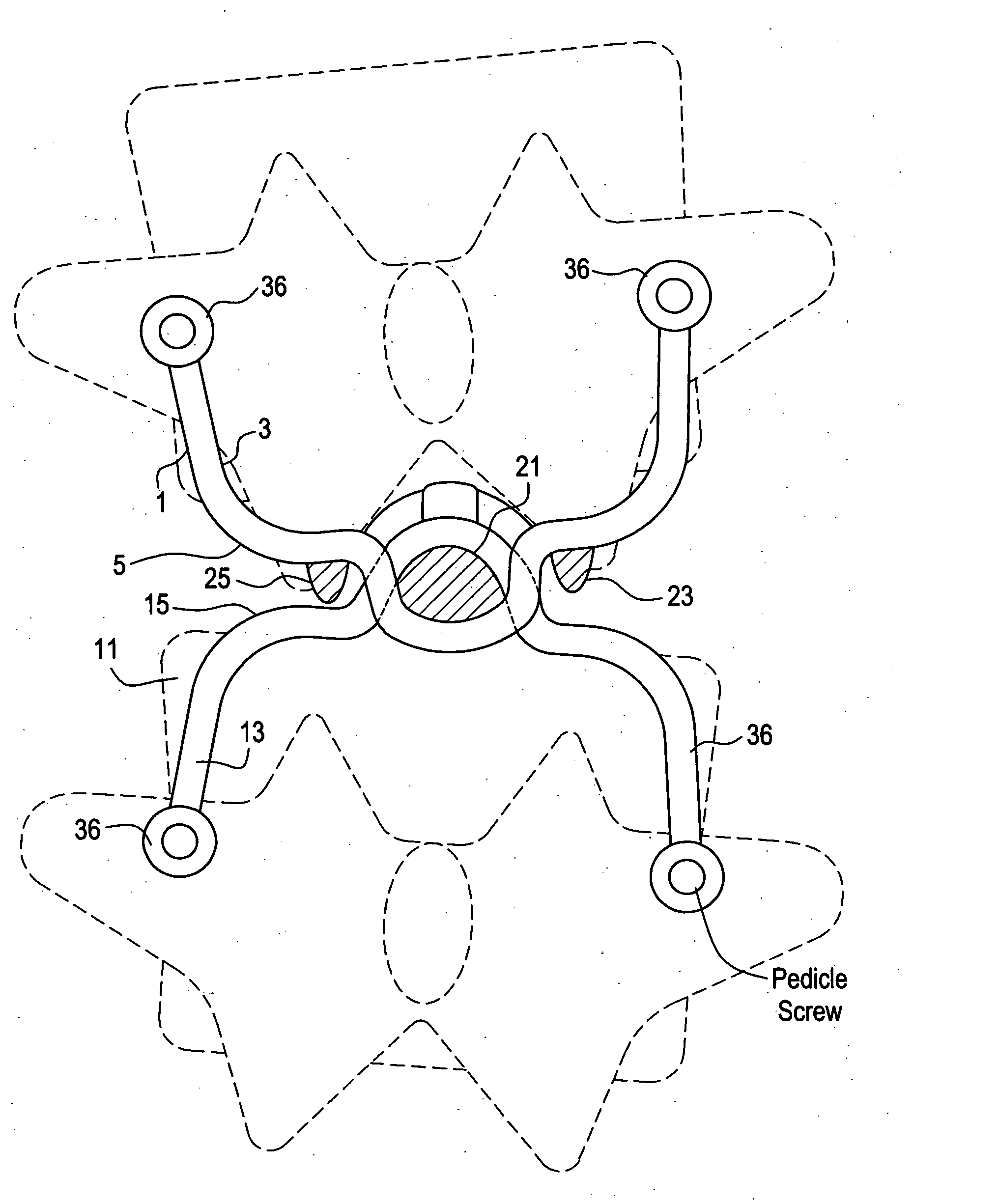
[0048] Now referring to FIG. 1, there is provided a prosthetic facet joint device comprising: [0049] a) a first upper component 1 adapted for fixation to a first upper vertebra comprising: [0050] i) a first inner side 3, and [0051] ii) a second outer side 5 facing away from the first side, and [0052] b) a second lower component 11 adapted for fixation to a second lower vertebra comprising: [0053] i) a first inner side 13, and [0054] ii) a second outer side 15 facing away from the first side,

wherein the first inner side of the first upper component opposes the first inner side of the second lower component at a first central location to form a first central interface, and

wherein the second outer side of the first upper component opposes the second outer side of the second lower component at a second lateral location to form a second interface, and

wherein the second outer side of the first component opposes the second outer side of the second component at a third lateral locatio...


PUM


Abstract

A prosthetic facet joint having compression springs interposed between articulating surfaces for providing gradual resistance to extreme movements.

Description

BACKGROUND OF THE INVENTION [0001] One of the most common surgical interventions in spine today is arthrodesis, or spine fusion, in which two or more adjacent vertebral bodies are fused together in order to alleviate pain associated with the disc(s) located between those vertebral bodies. Approximately 300,000 such procedures are performed annually in the United States alone. Clinical success varies considerably, depending upon technique and indications, and consideration must be given to the concomitant risks and complications. [0002] While spine fusion generally helps to eliminate certain types of pain, it has also been shown to decrease function by limiting the range of motion for patients in flexion, extension, rotation and lateral bending. Furthermore, it is believed that spine fusion creates increased stresses on (and, therefore, accelerated degeneration of) adjacent non-fused motion segments. Additionally, pseudoarthrosis, resulting from an incomplete or ineffective fusion, m...

Claims


Application Information

Patent Timeline
IPC IPC(8): A61F2/44A61B17/70
CPCA61B17/7064A61F2/4405A61F2002/30135A61F2002/30168A61F2002/30462A61F2002/30563A61F2002/30565A61F2002/30685A61F2220/0075A61F2230/0004A61F2230/0043A61F2002/30136
Inventor KWAK, SEUNGKYU DANIEL
Owner DEPUY SPINE INC (US)
Why Eureka
Try Eureka