Expandable intervertebral spacer method and apparatus

a technology of intervertebral spacer and expandable body, which is applied in the field of expandable intervertebral spacer devices, can solve the problems of increased risk of adverse effects, disc space collapse, and difficulty in restoring disc heigh

Inactive Publication Date: 2006-06-15
ALPINESPINE
View PDF38 Cites 763 Cited by
  • Summary
  • Abstract
  • Description
  • Claims
  • Application Information

AI Technical Summary

Benefits of technology

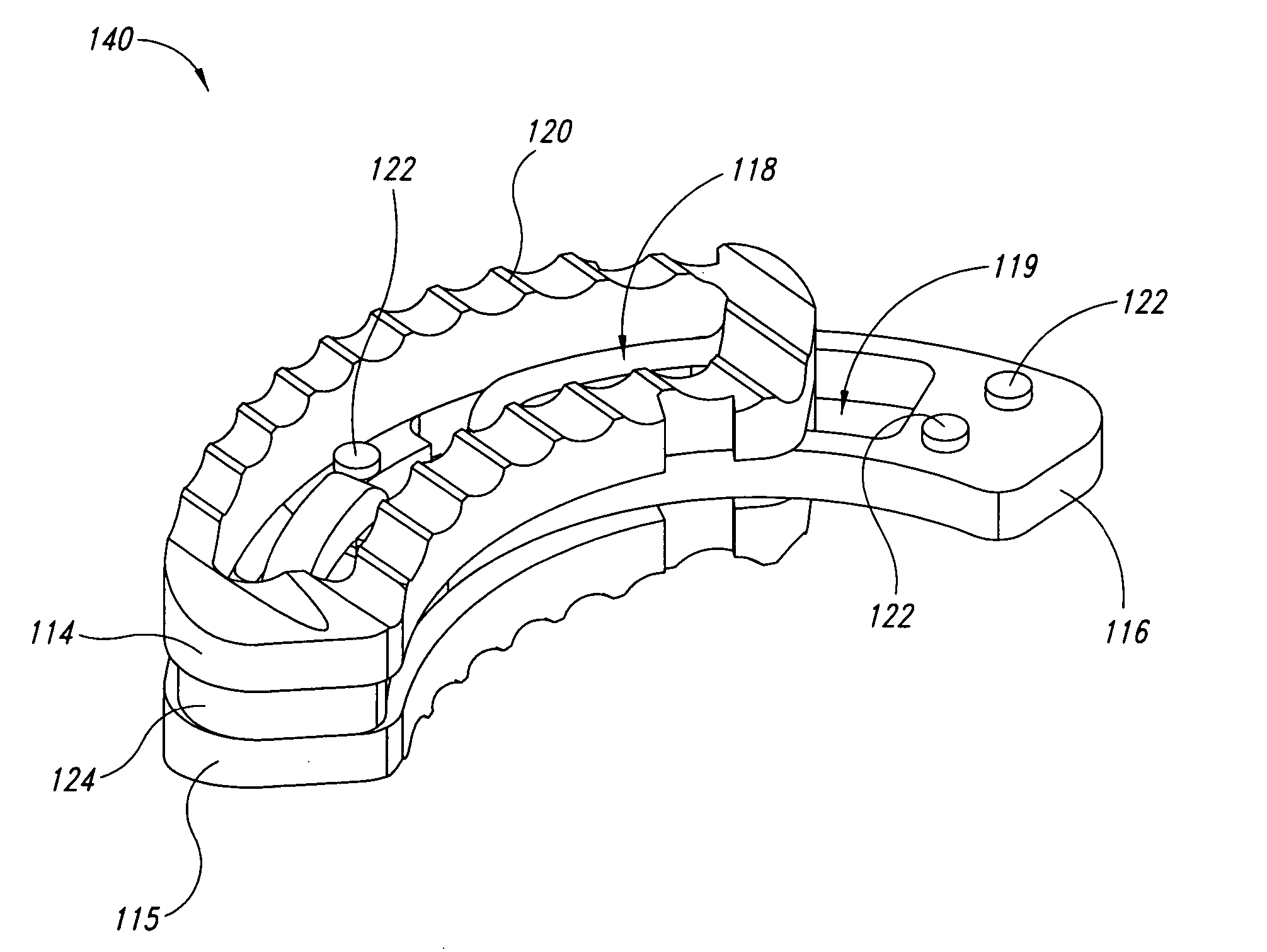
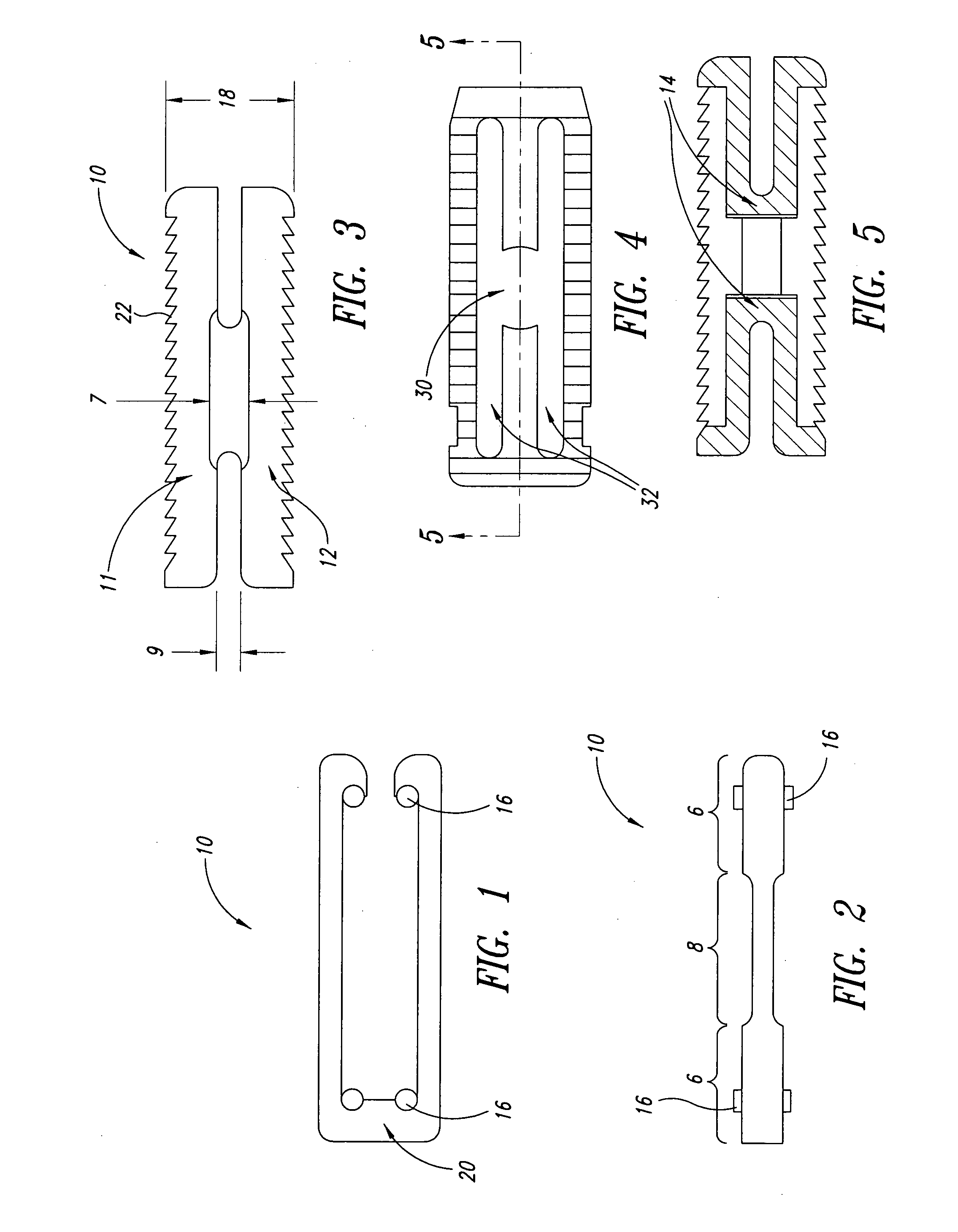
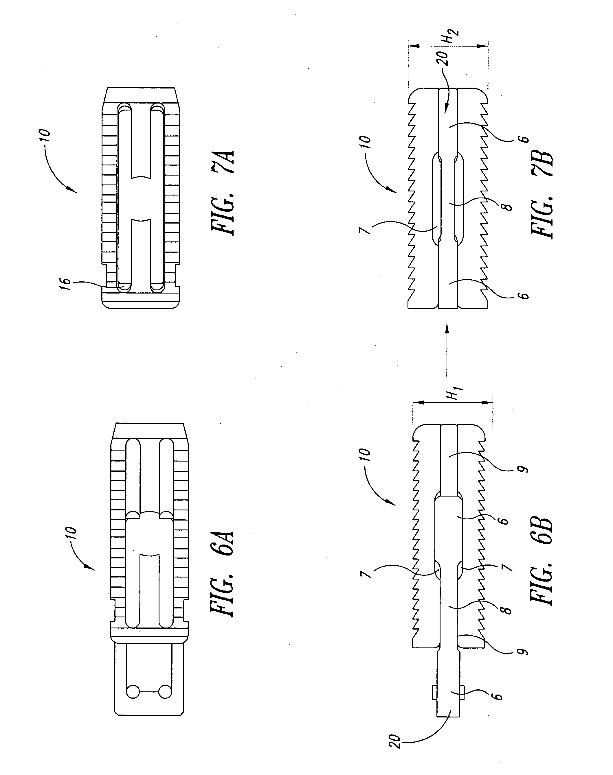
[0009] An expandable interbody spacer (IBS) device designed to restore the disc height between vertebral bodies is provided in accordance with the present invention. The expandable interbody spacer device is adapted for implanting between adjacent vertebral bodies of a human spine as a load-bearing replacement for a spinal disc. The expandable interbody spacer device has an integral, moveable expansion member or spreader, provided between two plates. The plates are connected by one or more connecting members that retain the plates in a position proximate to one another while allowing the plates to move from a first unexpanded position to a second expanded position upon activation of the expansion member. According to aspects of the invention, the interbody spacer device can be implanted in an unexpanded or collapsed configuration, and then expanded to full height by engaging the expansion member. In one embodiment, the interbody spacer device is machined such that space is left in the center of the device to receive BMP and morsalized bone to aid in fusion after implantation of the device. In other embodiments, the interbody spacer device may take various forms, for example, it may be cashew, rectangular or annular.

Problems solved by technology

Difficulty in restoring disc height has traditionally stemmed from the surgical procedure and the interbody implants that are used.
The surgical instruments are then removed to allow room for the implant; however, when the instruments are removed, the disc space collapses.
This serial insertion and removal of instruments and subsequent impaction of the implant results in increased risk of adverse effects.
The result has been the creation of a plethora of complex and expensive implants; many require special tools, involve screws that frequently result in cross threading, or include pop-up ratchet configurations that may fail when loaded.

Method used


Image

  • Expandable intervertebral spacer method and apparatus
  • Expandable intervertebral spacer method and apparatus
  • Expandable intervertebral spacer method and apparatus

Examples


Embodiment Construction

[0040] In the following description, certain specific details are set forth in order to provide a thorough understanding of various embodiments of the invention. However, one skilled in the relevant art will recognize that the invention may be practiced without one or more of these specific details, or with other methods, components, materials, etc. In other instances, well-known structures associated with intervertebral spacer devices and the spine have not been shown or described in detail to avoid unnecessarily obscuring descriptions of the embodiments of the invention.

[0041] Unless the context requires otherwise, throughout the specification and claims which follow, the word “comprise” and variations thereof, such as, “comprises” and “comprising” are to be construed in an open, inclusive sense, that is as “including, but not limited to.”

[0042] Reference throughout this specification to “one embodiment” or “an embodiment” means that a particular feature, structure or characteris...


PUM

PropertyMeasurementUnit
heightaaaaaaaaaa
lordodic angleaaaaaaaaaa
sizeaaaaaaaaaa

Abstract

An expandable interbody spacer (IBS) device designed to restore the disc height between vertebral bodies. The expandable interbody spacer device has an integral, moveable expansion member or spreader, provided between two plates. The plates are connected by one or more connecting members that retain the plates in a position proximate to one another while allowing the plates to move from a first unexpanded position to a second expanded position upon activation of the expansion member. According to aspects of the invention, the interbody spacer device can be implanted in an unexpanded or collapsed configuration, and then expanded to full height by engaging the expansion member. In other embodiments, the interbody spacer device may take various forms, for example, it may be cashew, rectangular or annular.

Description

BACKGROUND OF THE INVENTION [0001] 1. Field of the Invention [0002] The present invention is directed to an intervertebral spacer device, and more particularly, to an expandable intervertebral spacer device that may be applied to various existing surgical approaches, for example, posterior lumbar interbody fusion (PLIF), transforaminal lumbar interbody fusion (TLIF), anterior lumbar interbody fusion (ALIF), minimally invasive lumbar interbody fusion (MILIF), lateral interbody fusion, and oblique interbody fusion. [0003] 2. Description of the Related Art [0004] The cervical and lumbar portions of the spine are frequently fused to treat instability and degenerative diseases of the spine. There are many diverse approaches and a variety of indications available for lumbar interbody fusion. Despite the diverse approaches and indications, however, each approach generally targets restoration of disc height. [0005] Difficulty in restoring disc height has traditionally stemmed from the surgi...

Claims


Application Information

Patent Timeline
Patent Type & Authority Applications(United States)
IPC IPC(8): A61F2/44
CPCA61F2/4455A61F2/4465A61F2/447A61F2002/2835A61F2002/30062A61F2002/30133A61F2002/30428A61F2002/3055A61F2002/30571A61F2002/30578A61F2002/30784A61F2002/30818A61F2002/30904A61F2210/0004A61F2220/0025A61F2230/0015A61F2310/00017A61F2310/00023A61F2310/00161A61F2310/00179A61B17/56A61F2/44
Inventor ENSIGN, MICHAEL D.
Owner ALPINESPINE
Why Eureka
Try Eureka