Spinal disc space distractor

a distractor and spine disc technology, applied in the field of spine disc distractors, can solve the problems of difficulty in restoring the natural disc height, damage to the vertebrae or the vertebral endplate at the insertion site, and the risk of breaking of allograft products and so as to reduce the risk of breaking of allograft implants and other cages made from brittle materials during insertion, and the effect of correct placement of implants

Inactive Publication Date: 2005-08-11
DEPUY SYNTHES PROD INC
View PDF60 Cites 101 Cited by
  • Summary
  • Abstract
  • Description
  • Claims
  • Application Information

AI Technical Summary

Benefits of technology

[0013] The spinal disc distractor of the present invention is thus designed to distract disc space atraumatically with respect to both the vertebrae and the implant during endplate preparation, implant sizing, and implant insertion. The distractor may be used in a straight anterior, anterolateral, or lateral approach, and may be used in either an open or a laparoscopic procedure. Moreover, the distractor is designed to ensure the selection of an anatomically correct implant size by permitting the annulus to be fully stretched so that the largest possible implant may be inserted and compressed upon release of the vertebrae, thereby enhancing stability and assuring correct placement of the implant. Thus, the present invention permits disc height and lordosis to be restored. The jaws are shaped and configured to preserve the endplate and the vertebral body during distraction, as well as to permit insertion of an implant during distraction. The risk of breakage of allograft implants and other cages made from brittle materials during insertion is thereby reduced.

Problems solved by technology

However, the technique for the insertion of these implants generally does not achieve distraction because of their height limitations, thus making it difficult to restore the natural disc height.
The force necessary to insert these implants (such as by drilling and tapping) may cause damage to the vertebrae or vertebral endplates at the insertion site.
Moreover, allograft products and cages made out of other brittle materials (e.g., carbon fiber and ceramics) may break during insertion, particularly when distraction is not used and external force is necessary to insert the implant.
Threaded cages on the other hand do not restore lordosis, and do not allow for atraumatic distraction to restore disc height.

Method used


Image

  • Spinal disc space distractor
  • Spinal disc space distractor
  • Spinal disc space distractor

Examples


Embodiment Construction

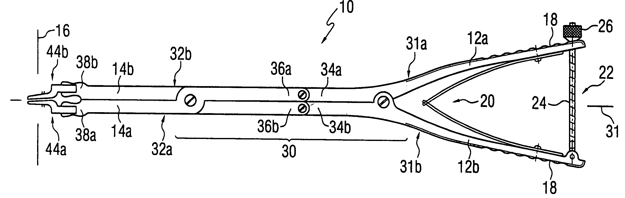
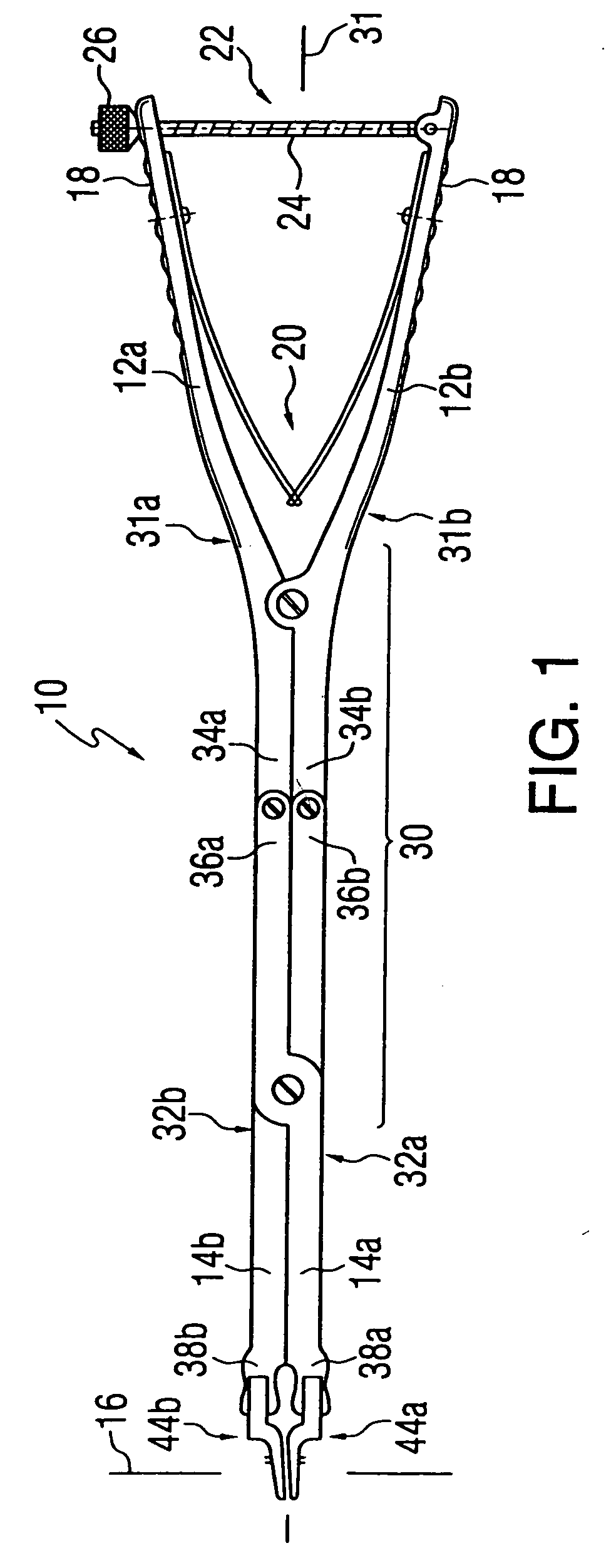
[0032] In accordance with the principles of the present invention, a distractor 10 is provided with a pair of handles 12a, 12b movable with respect to each other to actuate a pair of jaws 14a, 14b coupled thereto, as shown in FIG. 1. Although distractor 10 may be used for a variety of procedures, a preferred procedure for which distractor 10 is used is spinal disc distraction. Thus, distractor 10 is preferably configured such that actuation of handles 12 (12a, 12b) moves jaws 14 (14a, 14b) apart substantially along distraction axis 16 to a working position corresponding to the desired resulting relative position of the endplates. For example, the blades may be moved to a substantially parallel or lordotic position to separate adjacent vertebrae to be treated.

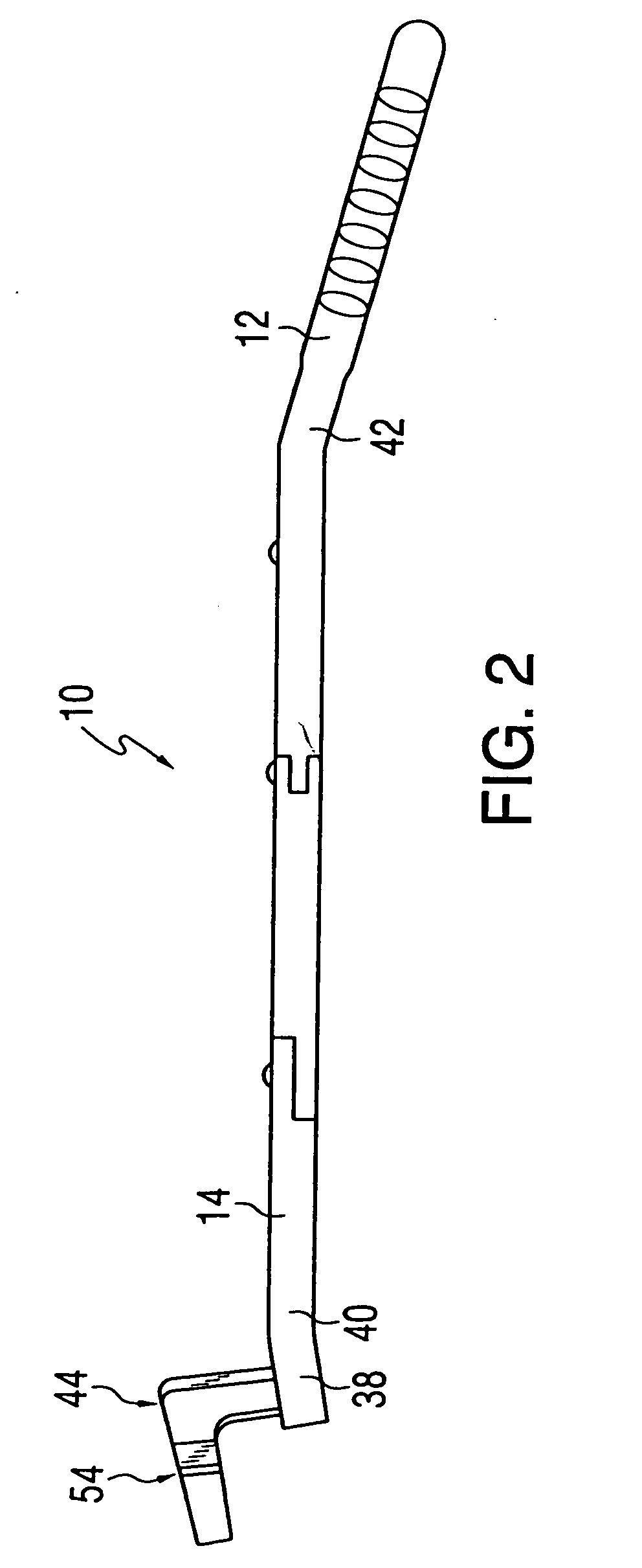
[0033] In order to be optimally useful for use in an anterior approach, handles 12 and jaws 14 are configured to move jaws 14 apart along distraction axis 16 a sufficient amount to adequately separate adjacent vertebrae to be t...


PUM


Abstract

A distractor for separating adjacent elements, such as vertebrae. The distractor preferably has a scissors-type distracting mechanism, either in a simple scissors or double-acting scissors configuration. A set of blades is provided on each jaw such that an implant may be inserted between the spaced apart blades. The set of blades includes at least two blades.

Description

CROSS-REFERENCE TO RELATED APPLICATION [0001] This application is a continuation of copending U.S. patent application Ser. No. 09 / 879,911, filed Jun. 14, 2001, which is a continuation of U.S. patent application Ser. No. 09 / 411,161, filed Oct. 1, 1999, now U.S. Pat. No. 6,261,296, which claims priority to U.S. Provisional Application No. 60 / 102,669, filed Oct. 2, 1998, which are incorporated by reference herein in their entirety.FIELD OF THE INVENTION [0002] The present invention relates to a device and method for spreading apart adjacent vertebrae of a vertebral column so that an implant may be inserted therebetween. More particularly, the present invention relates to a distractor device shaped and configured for minimally invasive insertion and use, such as for distraction of vertebrae using an anterior or anterolateral approach. BACKGROUND OF THE INVENTION [0003] Back pain can be caused by either one or a combination of the following: a loss of disc height, compression of nerve ro...

Claims


Application Information

Patent Timeline
Patent Type & Authority Applications(United States)
IPC IPC(8): A61B17/00A61B17/02A61B17/56A61B17/28A61F2/28
CPCA61B17/0206A61B17/025A61B2017/00738A61B2017/00473A61B17/2804
Inventor AEBI, MAXSTEFFEN, THOMASPAUL, DAVID C.COTTLE, WILLIAM A.SCHENK, BEAT
Owner DEPUY SYNTHES PROD INC
Why Eureka
Try Eureka