

Bone anchor apparatus and method
- Summary
- Abstract
- Description
- Claims
- Application Information
AI Technical Summary
Benefits of technology
Problems solved by technology
Method used
Image

Examples
embodiment 200
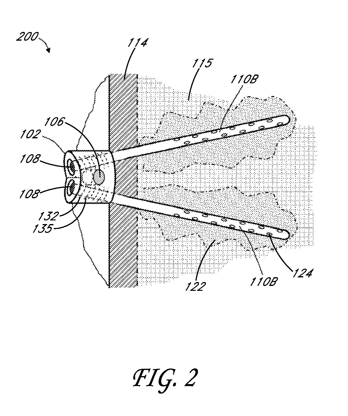
[0039]Turning now to FIG. 2, an alternative anchor embodiment 200 is illustrated which is similar in some respects to that of FIG. 1. As can be seen, the anchor 200 can include a head 102 having a plurality of bores 108. The bores 108 can be configured to receive extension elements 110B. One way in which the anchor 200 is different from that shown in FIG. 1 is that both of the extension elements 110B are separable from the anchor head portion 102. In addition, the head portion 102 also can include a bore 106 for receiving a dynamic stabilization apparatus as described above. The injection of bone cement 122 can also be utilized as described in the embodiment of FIG. 1.
embodiment 300
[0040]FIG. 3 illustrates an alternative anchor embodiment 300 which is similar to that of FIG. 2 except that both the first and second extension elements 140 are configured as bone screws and can be used without bone cement. The screw extension elements 140 can be configured with any type of head portion 142 for engaging with a driving tool (not shown). Such an anchor can be useful in weakened osteoporotic bone where multiple small screws would be preferred over a larger screw. Also, such multiple screws would be generally preferred in pedicles of certain vertebral bodies where two smaller diameter screws would fit within a narrow cross-section pedicle better than one larger diameter screw.
[0041]In general, the disclosure provides a revisable anchor system for anchoring within a vertebral body. Some embodiments of an anchor system can comprise an elongated body having a proximal and a distal end, a first extension portion extending at a first angle from the proximal end, and a secon...
embodiment 400
[0044]Referring now to FIG. 4, an alternative anchor embodiment 400 which can be utilized in methods described herein is illustrated. The anchor 400 can include a head portion 102, an intermediate portion 425, an extension portion 405, and a plurality of extension elements 410. The head portion 102 can allow injection of bone cement 122 therethrough into extension portion 405. Extension portion 405 can comprise a sleeve, such as a metal sleeve, polymer sleeve or the like that can be removed or left in place in a revision procedure. The extension portion 405 can be integral with the head 102 and intermediate 425 portions, as shown, or may be separable therefrom. The anchor head 102 can allow for a plurality of extension elements 410 to be inserted into the bone. The anchor head 102 can also include a bore 106 to secure a spine treatment apparatus indicated at 420. The plurality of extension elements 410 and the bone cement can allow for secure anchoring of the implant and attached sp...
PUM
 Abstract
Description
Claims
Application Information