Apparatus and method for efficient dispensing of fluids from a container

a technology of fluid dispensing apparatus and container, which is applied in the direction of liquid spraying apparatus, liquid transfer device, packaging, etc., to achieve the effect of enhancing the ability of the suction hos

Inactive Publication Date: 2006-06-22
MERTINS LEE
View PDF15 Cites 12 Cited by
  • Summary
  • Abstract
  • Description
  • Claims
  • Application Information

AI Technical Summary

Benefits of technology

[0008] This invention also provides a rounded filter attached to the end of the suction hose which matches the bottom corner of the container and enhances the ability of the suction hose to gather fluid from low levels in the container.

Problems solved by technology

The guiding rod does not allow the bottom corner of the container to move; therefore, the container tilts toward the bottom corner forcing a pooling of liquid within reach of the suction hose.

Method used


Image

  • Apparatus and method for efficient dispensing of fluids from a container
  • Apparatus and method for efficient dispensing of fluids from a container
  • Apparatus and method for efficient dispensing of fluids from a container

Examples


first embodiment

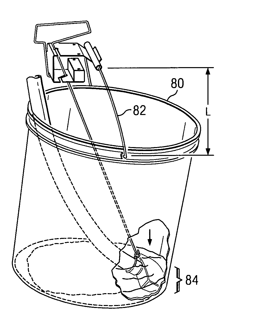
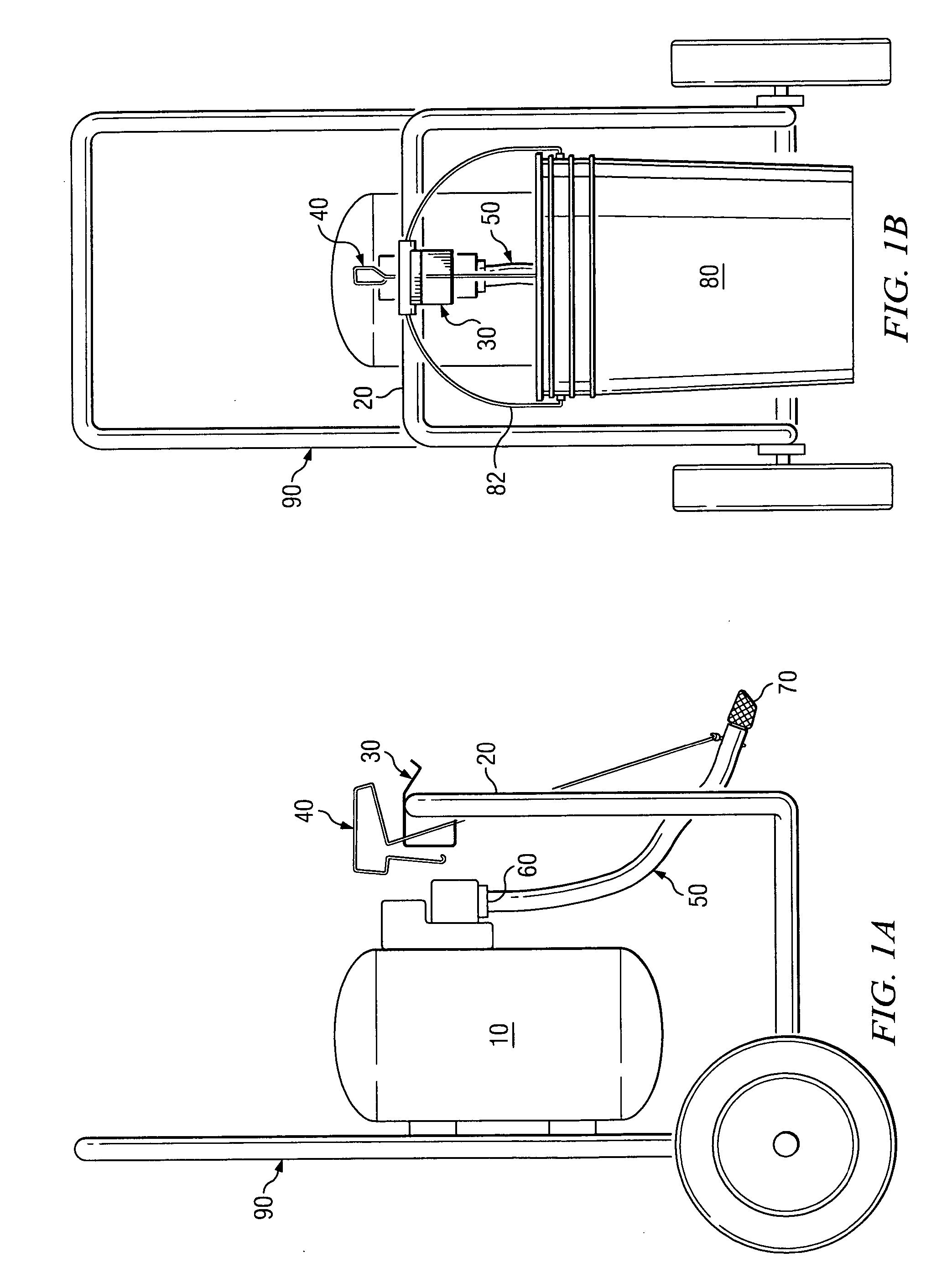
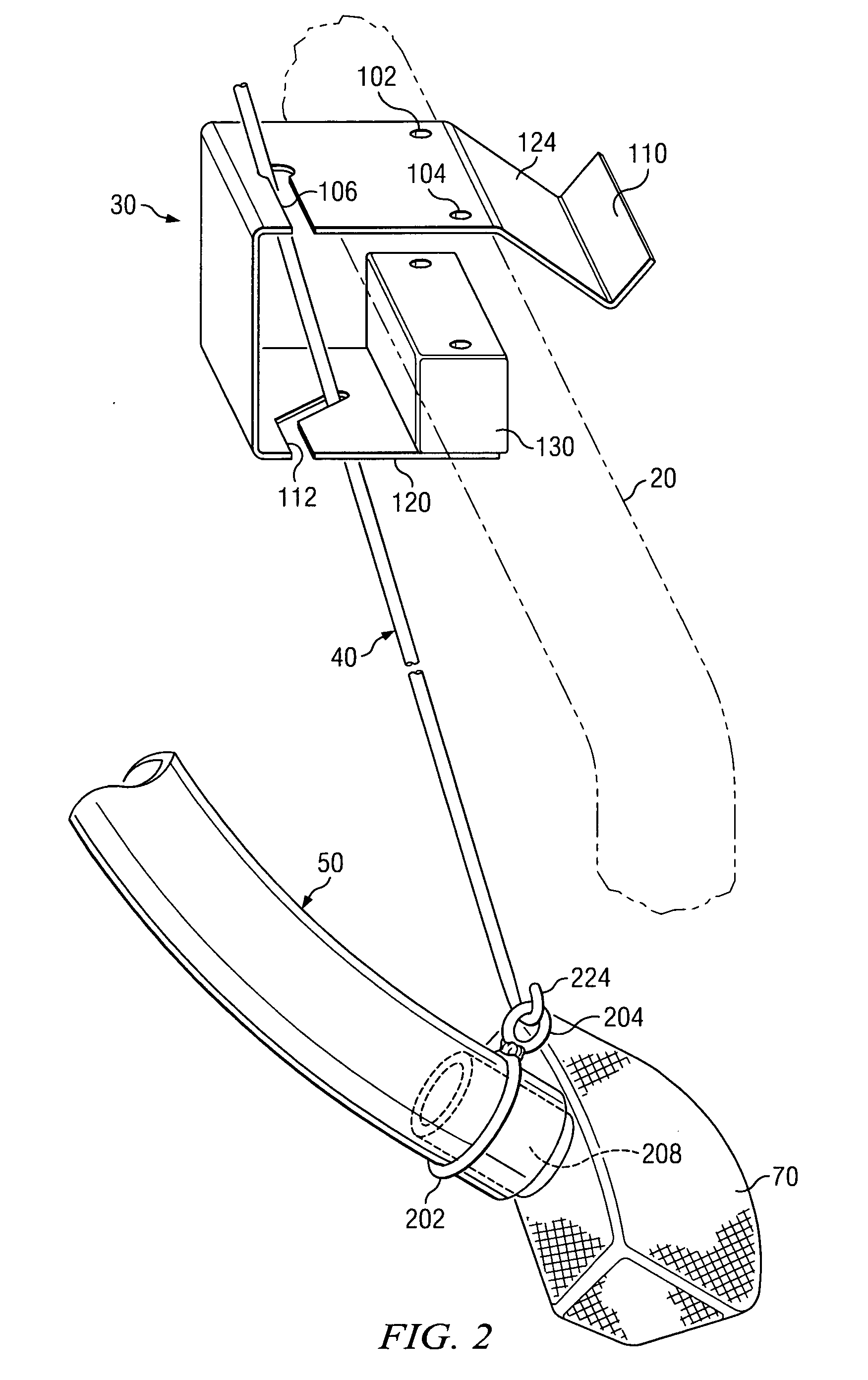
[0036] Pressure sprayers in general include a motor, a compressor and a coupling for attachment of a suction hose to draw liquid from a container. Referring now to FIGS. 1A and 1B, a side and front view of the device is shown generally in relation to pressure sprayer 10, mounted onto movable cart 90 where the frame of the movable cart includes overhead bar 20 supporting container 80. Movable cart 90 allows easy transportation of the sprayer and container. Overhead bar 20 is located in the front of movable cart 90. The overhead bar serves the purpose of supporting bracket 30 on which handle 82 of container 80 may be hung.

[0037] Pressure sprayer 10 in the preferred embodiment is a commercial pressure sprayer which includes models manufactured by companies such as Campbell-Hausfeld and Wagner. In the preferred embodiment, the container is a 5-gallon bucket with a metallic semicircular pivoted handle made of heavy gauge steel wire. In the preferred embodiment, the fluid in the bucket i...

second embodiment

[0057] Depicted in FIG. 10 is a second exemplary embodiment of the present invention. FIG. 10 shows pressure sprayer 15 mounted on movable cart 95. Affixed to pressure sprayer 15 is bracket 510 and hose 55 connected to the low pressure fluid inlet of pressure sprayer 15. Guiding rod 40 is inserted between openings in bracket 510 and attached to hose 55. Bracket 510 of FIG. 10 also provides an area for hanging container 80. Because the weight of a full container of fluid is significant, the bracket is preferably made of a sturdy material such as rigid plastic or metal. Bracket 510 of the second embodiment is not fastened to an overhead bar, but is instead fastened the bottom portion of the pressure sprayer by nuts or screws.

[0058]FIGS. 11A and 11B depict a front view and an isometric view of bracket 510 of the second exemplary embodiment. Bracket 510 includes two folded fingers 518 and 520, notch 512, upward angled piece 516, flat piece 524 with slot 514 extending from it to the end ...


PUM


Abstract

The invention provides an apparatus and method for tipping and efficiently drawing fluid from a bucket or container. In one exemplary embodiment, the apparatus includes a frame, a bracket attached to the frame, a pressure sprayer connected to a suction hose, and a guiding rod placed through the bracket and connected to the suction hose. In another exemplary embodiment, the device includes a bracket attached directly to the pressure sprayer. In one example, the bracket is made of a rigid metal alloy capable of supporting 5 gallons of paint. In use, the sprayer draws liquid from the container through the suction hose. As the container is emptied of fluid, the spring action provided by the handle raises the container. The guiding rod does not allow the bottom corner of the container to move; therefore, the container tilts toward the bottom corner forcing a pooling of liquid within reach of the suction hose. This invention also provides a rounded filter attached to the end of the suction hose which matches the bottom corner of the container and enhances the ability of the suction hose to gather fluid from low levels in the container.

Description

FIELD OF THE INVENTION [0001] This invention relates to an apparatus and method for efficient dispensing of fluids from a container. In particular, the invention relates to an apparatus and method that permits a majority of fluid to be removed from a container. More particularly, the invention relates to an apparatus and method that releasably holds the suction hose of a pressure sprayer to the bottom corner of a container and causes it to tilt as the fluid in the container is removed by the spring contraction of the container handle. BACKGROUND OF THE INVENTION [0002] Pressure sprayers are typically used for a number of projects which require dispensing of liquids from containers. Pressure sprayers are generally mounted on a movable cart to allow for portability. They include at a minimum a motor, compressor, suction hose, fluid container and a high pressure hose and nozzle. [0003] Typically, fluid is drawn from the container through a hose connected to the low pressure side of the...

Claims


Application Information

Patent Timeline
Patent Type & Authority Applications(United States)
IPC IPC(8): B67D5/64B67D7/84
CPCB05B9/007B05B9/0403B05B15/005B05B15/008B05B15/30B05B15/40
Inventor MERTINS, LEE
Owner MERTINS LEE
Why Eureka
Try Eureka