
System and method for measuring clearance between two objects

Active Publication Date: 2006-06-22
GENERAL ELECTRIC CO
View PDF9 Cites 49 Cited by
  • Summary
  • Abstract
  • Description
  • Claims
  • Application Information

AI Technical Summary

Problems solved by technology

Unfortunately, existing direct measurement techniques employing a single probe for a single target object are relatively inaccurate where the target object changes its geometry during the course of measurement.
Such changes may result in a drift in the calibration of the probe.
Further, noise due to thermal distortions in the wire connecting the probe to a clearance control unit may also results in inaccurate measurements.
Unfortunately, these sensor systems are not workable for in-service measurements due to the noise and drift generated by changes in geometry of the parts.
As the parts become worn during service, the offline measurements become ineffective for in-service clearance control.

Method used


Image

  • System and method for measuring clearance between two objects
  • System and method for measuring clearance between two objects
  • System and method for measuring clearance between two objects

Examples


Embodiment Construction

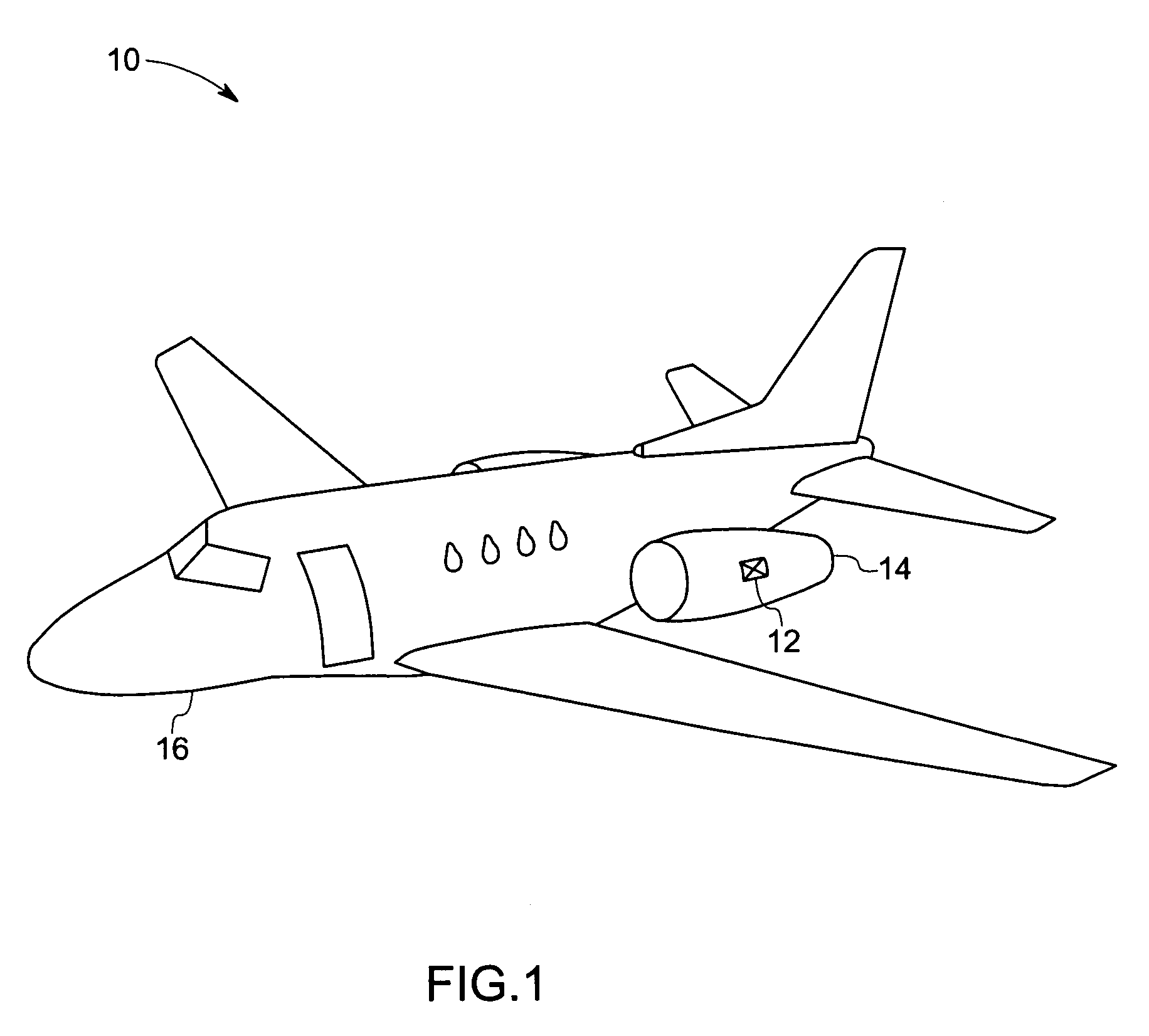
[0021] As discussed in detail below, embodiments of the present technique function to provide an accurate measurement of clearance between two objects in various systems such as an aircraft engine, a steam turbine, and so forth. Referring now to the drawings, FIG. 1 illustrates an aircraft 10 having a sensor system 12 disposed in an aircraft engine 14 coupled to a body or frame 16 of the aircraft 10. In the illustrated embodiment, the sensor system 12 is configured for measuring a clearance between two objects, such as the clearance between a turbine blade and a shroud in the aircraft engine 14 as will be described in detail below with reference to FIG. 2.

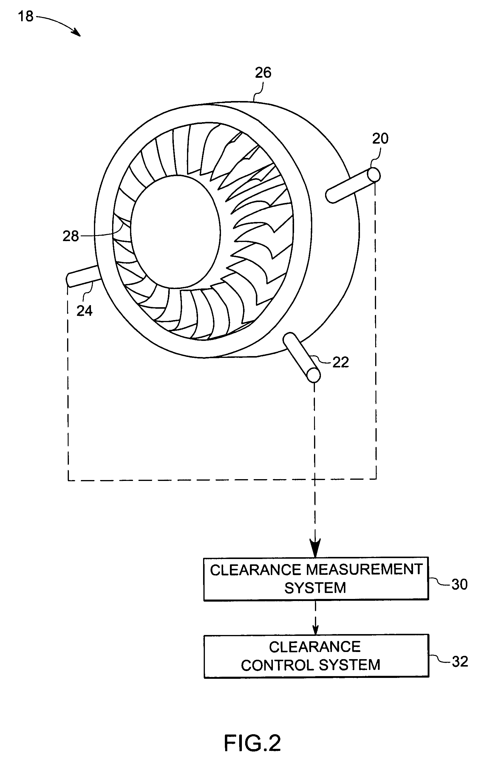
[0022]FIG. 2 illustrates a rotating component, such as a turbine 18 of the aircraft engine 14, having a plurality of sensors 20, 22, and 24 for measuring the clearance between a casing 26 and a plurality of turbine blades 28 disposed within the casing 26. In this embodiment, three sensors 20, 22, and 24 are employed at three diffe...


PUM


Abstract

A system for measuring clearance between a first object and a second object is provided. The system includes a sensor configuration to generate a first signal representative of a first sensed parameter and a second signal representative of a second sensed parameter. The system also includes a clearance measurement unit configured to process the first and second signals based upon a ratiometric technique to calculate clearance between the first and second objects.

Description

BACKGROUND [0001] The invention relates generally to sensor systems, and more particularly to a sensor system for measuring a clearance between two objects through a ratiometric technique. [0002] Various types of sensors have been used to measure the distance between two objects. In addition, these sensors have been used in various applications. For example, a turbine has a turbine blade that is disposed adjacent to a shroud. The clearance between the turbine blade and the shroud varies depending on the temperature of the turbine blade. For example, the clearance between the shroud and the turbine blade is greatest when the turbine is cold and gradually decreases as the turbine heats up. It is desirable that a gap or clearance between the turbine blade and the shroud be maintained for safe and effective operation of the turbine. A sensor may be disposed within the turbine to measure the distance between the turbine blade and the shroud. The distance may be used to direct movement of...

Claims


Application Information

Patent Timeline
IPC IPC(8): G01B11/14G01R27/26
CPCG01B7/14
Inventor BALASUBRAMANIAM, MAHADEVANANDARAWIS, EMAD ANDARAWISRUUD, JAMES ANTHONYDASGUPTA, SAMHITASHAH, MINESH ASHOK
Owner GENERAL ELECTRIC CO
Features
  • Generate Ideas
  • Intellectual Property
  • Life Sciences
  • Materials
  • Tech Scout
  • Unparalleled Data Quality
  • Higher Quality Content
  • 60% Fewer Hallucinations
Learn More