Three-phase ac-to-dc-to-ac converter

a power converter and three-phase technology, applied in the field of power converters, can solve the problems of substantial power loss, substantial diminution of efficiency, and power loss of six switches of the dc-to-ac converter circuit, and achieve the effect of improving the efficiency of the three-phase ac-to-dc-to-ac power converter system and avoiding power loss through these switches

Inactive Publication Date: 2006-06-22
SANKEN ELECTRIC CO LTD
View PDF2 Cites 45 Cited by
  • Summary
  • Abstract
  • Description
  • Claims
  • Application Information

AI Technical Summary

Benefits of technology

[0008] Thus, closed when the three-phase dc-to-ac converter circuit is driven in synchronism with the three-phase ac input voltages, the bypass switch provides a bypass connection between the preselected ac input terminal and the preselected ac output terminal. Let it be supposed for instance that the bypass switch has directly connected the first ac input terminal and first ac output terminal. Then the effective current demanded by the loaded connected to the first ac output terminal will be supplied, either in part or i

Problems solved by technology

There have been some problems left unresolved with the prior art three-phase power converter outlined above, causing a substantive diminution of its efficiency.
One of the problems is that the six switches of the dc-to-ac c

Method used


Image

  • Three-phase ac-to-dc-to-ac converter
  • Three-phase ac-to-dc-to-ac converter
  • Three-phase ac-to-dc-to-ac converter

Examples


embodiment

of FIG. 7

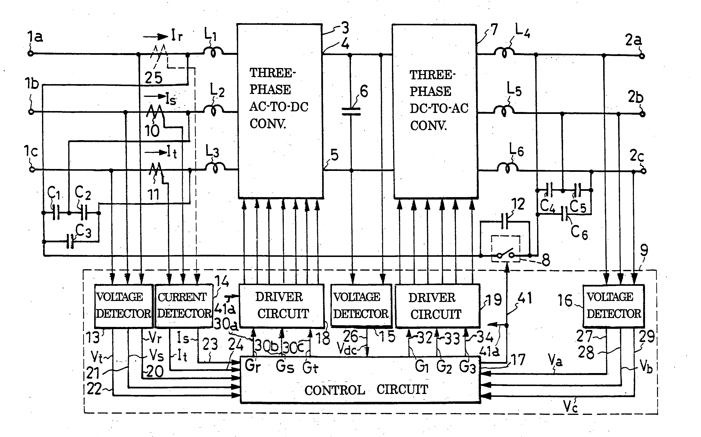
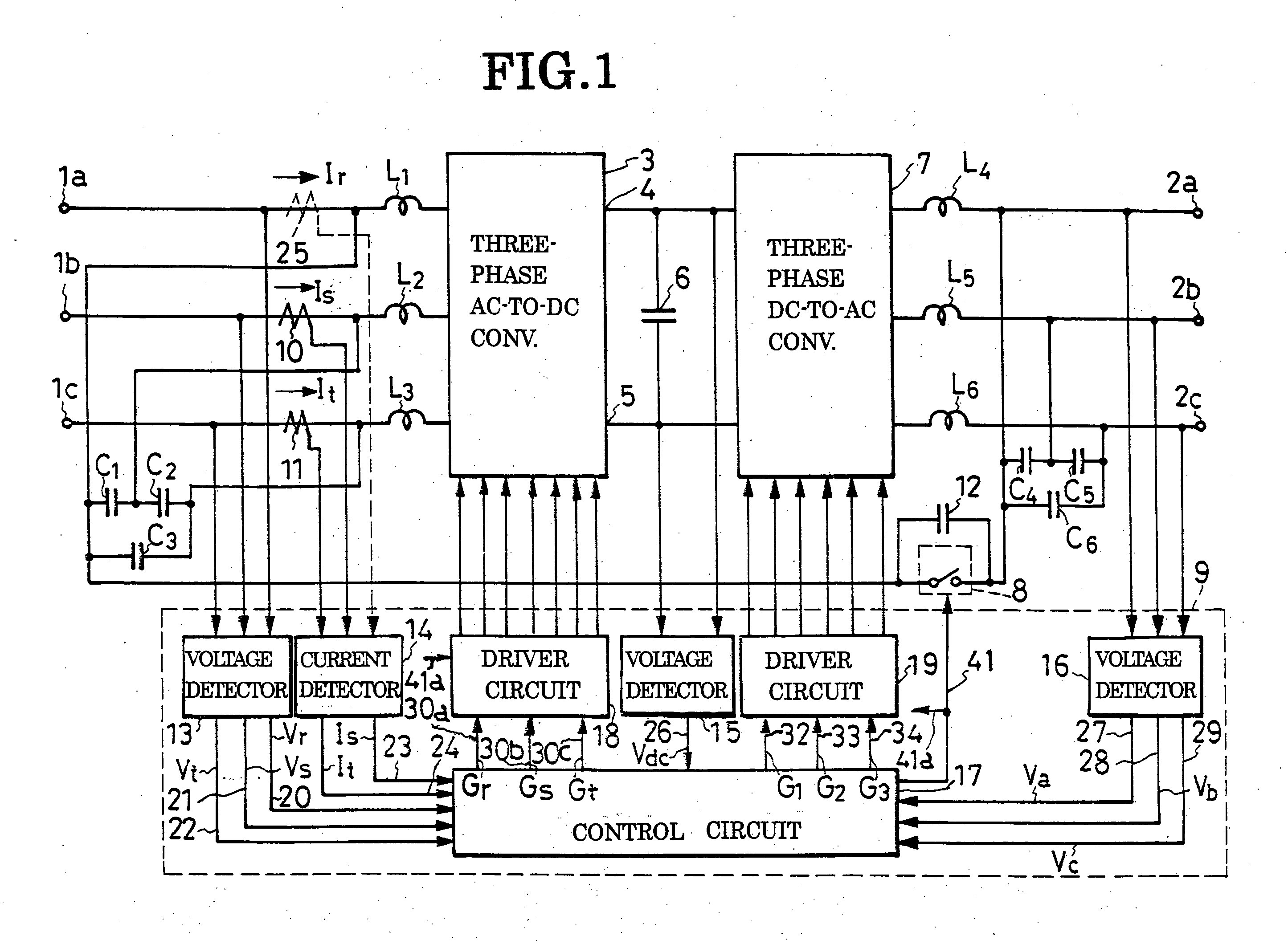
[0130] This alternate embodiment of the invention features a modified ac-to-dc converter control circuit 36a for use in the three-phase power converter system of FIGS. 1-5 in substitution for the original ac-to-dc converter control circuit 36, FIG. 3. All the other details of construction are as previously set forth with reference to FIGS. 1-5 in conjunction with the first disclosed embodiment. A comparison of FIGS. 3 and 7 will reveal, however, that the modified ac-to-dc converter control circuit 36a is constructed to input the detected R-phase input current Ir for production of the R-phase current control signal Vir, instead of creating this signal from the S- and T-phase current control signals Vis and Vit as in the ac-to-dc converter control signal generator circuit 63, FIG. 5, of the first embodiment. It is therefore understood that the modified ac-to-ac converter control circuit 36a presupposes use of an R-phase current detector indicated by the broken lines in FIG. 1...


PUM


Abstract

A non-outage power supply system comprises three-phase ac input terminals and three-phase ac output terminals, between which there are sequentially connected a three-phase ac-to-dc converter circuit, a capacitor, and a three-phase dc-to-ac converter circuit. A bypass switch is connected between a preselected one of the three-phase ac input terminals and a preselected one of the three-phase ac output terminals. A bypass switch control circuit holds the bypass switch closed when the three-phase ac inputs are in phase with the three-phase ac outputs, and open when they are not. Part or all of the effective current demanded by the load bypasses the three-phase dc-to-ac converter circuit when the bypass switch is closed, with a consequent reduction of power loss.

Description

CROSS REFERNCE TO RELATED APPLICATIONS [0001] This application claims priority to Japanese Patent Application No. 2004-365502, filed Dec. 17, 2004. BACKGROUND OF THE INVENTION [0002] This invention relates to power converters, and particularly to those capable of three-phase ac-to-dc, and back to three-phase ac, conversion. [0003] Japanese Unexamined Patent Publication No. 2000-116137 teaches a three-phase power converter that is believed by this applicant to be closest to the instant invention. This prior art power converter comprises a three-phase ac-to-dc converter circuit connected to a set of three-phase ac inputs via inductors, a capacitor connected between the pair of dc outputs of the three-phase ac-to-dc converter circuit, and a three-phase dc-to-ac converter circuit connected between the capacitor and a set of three-phase ac outputs. [0004] The three-phase ac-to-dc converter circuit comprises six diodes in three-phase bridge connection and six ac-to-dc conversion switches ...

Claims


Application Information

Patent Timeline
IPC IPC(8): H02M5/45H02M5/458H02M7/12H02M7/48
CPCH02M5/4585
Inventor SATO, SHINJINAGAMATSU, FUMIOKANATA, TAKAHIROFUSE, YUJIKAWAUCHI, SHOICHIIYAMA, OSAMU
Owner SANKEN ELECTRIC CO LTD
Why Eureka
Try Eureka