Pleisiochronous repeater system and components thereof

a repeater system and pleisiochronous technology, applied in the field of high-speed signaling, can solve the problems of unsatisfactory and often even unacceptable pleisiochronous repeater systems

Active Publication Date: 2006-06-22
THE UNITED STATES OF AMERICA AS REPRESENTED BY THE SECRETARY OF THE NAVY +1
View PDF11 Cites 18 Cited by
  • Summary
  • Abstract
  • Description
  • Claims
  • Application Information

AI Technical Summary

Problems solved by technology

This result is undesirable and often even unacce

Method used


Image

  • Pleisiochronous repeater system and components thereof
  • Pleisiochronous repeater system and components thereof
  • Pleisiochronous repeater system and components thereof

Examples


Embodiment Construction

)

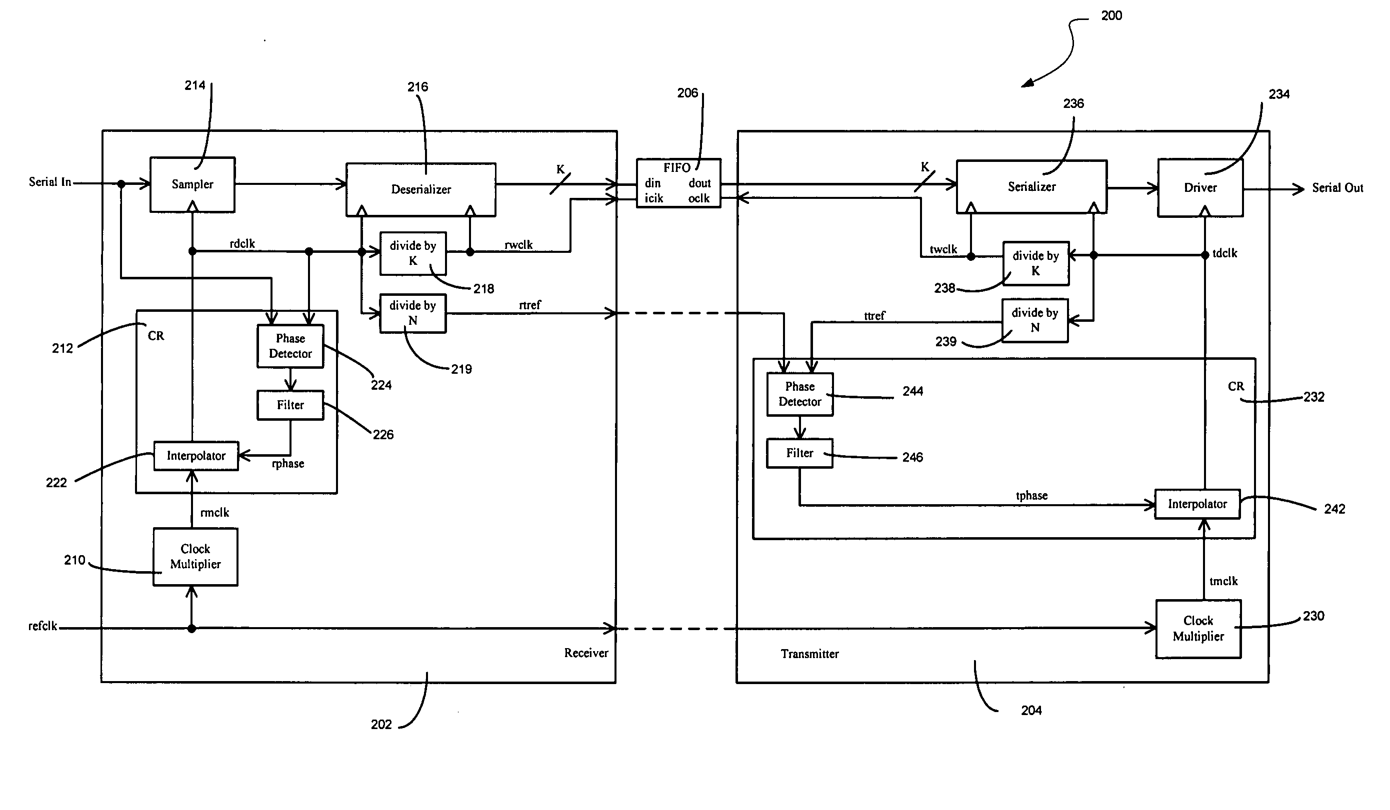
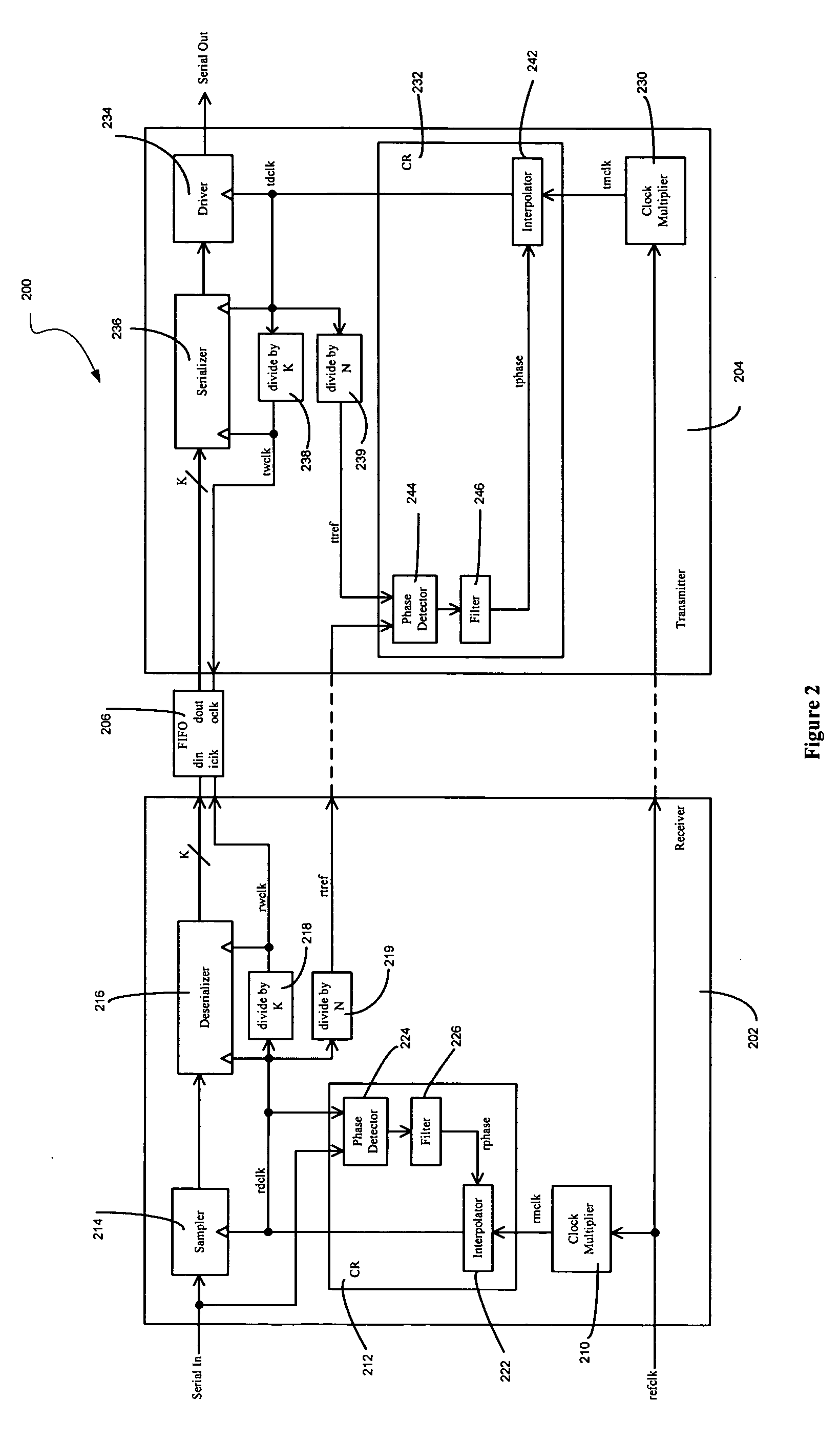
[0019] A pleisiochronous repeater system and components thereof are disclosed. In one particular exemplary embodiment, a pleisiochronous repeater system component may be realized as a receiver circuit comprising a clock multiplier that multiplies a reference clock signal by an integer multiple to generate a data clock signal. The receiver circuit may also comprise a divider circuit that generates, based at least in part upon the data clock signal, a timing reference signal having a frequency that is not an integer divisor of a frequency of the reference clock signal.

[0020] In accordance with another particular exemplary embodiment, a pleisiochronous repeater system component may be realized as a transmitter circuit comprising a clock multiplier that multiplies a reference clock signal by an integer multiple to generate a data clock signal. The transmitter circuit may also comprise a divider circuit for generating, based at least in part upon the data clock signal, a timing referen...


PUM


Abstract

A pleisiochronous repeater system and components thereof are disclosed. In one particular exemplary embodiment, a pleisiochronous repeater system component may be realized as a receiver circuit comprising a clock multiplier that multiplies a reference clock signal by an integer multiple to generate a data clock signal. The receiver circuit may also comprise a divider circuit that generates a timing reference signal having a frequency that is not an integer divisor of a frequency of the reference clock signal.

Description

FIELD OF THE DISCLOSURE [0001] The present disclosure relates generally to high speed signaling and, more particularly, to a pleisiochronous repeater system and components thereof. BACKGROUND OF THE DISCLOSURE [0002] All traditional clock multipliers exhibit some residual phase modulation of a multiplied clock at the frequency of a reference clock signal. The process of clock recovery in a receiver or a transmitter will cause a phase error appearing on the multiplied clock to be sampled at a frequency that is equal to a timing reference signal. This sampled phase error appears directly on the phase of the timing reference signal. The magnitude of this phase error is a function of a phase difference between the timing reference signal and the reference clock signal at the sampling instant. The shape of the function is a characteristic intrinsic to the clock multiplier. [0003] A transmitter clock recovery loop operates based upon phase differences between timing reference signals so a...

Claims


Application Information

Patent Timeline
IPC IPC(8): H04L25/60H04L7/00
CPCH03L7/0812H04L7/0012H04L7/0025H04L7/0091H04L7/005
Inventor PALMER, ROBERT E.GREER, THOMAS H. IIITELL, STEPHEN G.
Owner THE UNITED STATES OF AMERICA AS REPRESENTED BY THE SECRETARY OF THE NAVY
Why Eureka
Try Eureka