Height-and angle-adjustable motion disc implant

a motion disc and angle adjustment technology, applied in the field of heightand angle adjustment of motion disc implants, to achieve the effect of preventing stenosis or ankylosis

Inactive Publication Date: 2006-06-22
DEPUY SPINE INC (US)
View PDF34 Cites 288 Cited by
  • Summary
  • Abstract
  • Description
  • Claims
  • Application Information

AI Technical Summary

Benefits of technology

[0007] The implant of the present invention is advantageous because it can be inserted into the spine at a first height, and then adjusted to a second height to meet the needs of a particular patient.
[0008] In a first preferred embodiment, the height or angle of the implant is adjusted intra-operatively in order to fine tune the implant to the surgical needs of the patient. For example, such adjustment may allow precise tensioning of the annulus fibrosus, thereby preventing stenosis or ankylosis. In some embodiments, when the angle is adjusted, it is adjusted in either the coronal or saggital plane.

Problems solved by technology

For example, because of the implantation is an inexact procedure, there may be times when the implanted disc is to tall or too short, or there is improper angulation.

Method used


Image

  • Height-and angle-adjustable motion disc implant
  • Height-and angle-adjustable motion disc implant
  • Height-and angle-adjustable motion disc implant

Examples


Embodiment Construction

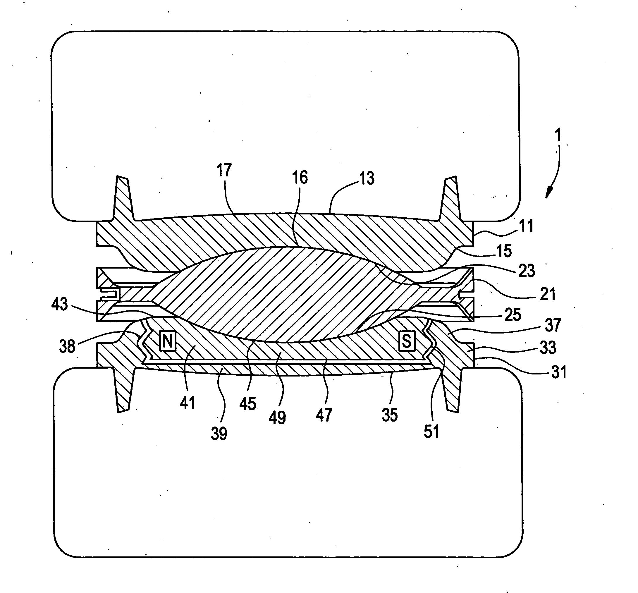
[0034] Now referring to FIG. 1, there is provided an intervertebral motion disc 1 comprising:

a) a first prosthetic vertebral endplate component 11 comprising:

[0035] i) an outer surface 13 adapted to mate with a first vertebral body, [0036] ii) an inner surface 15 having a first articulation surface 16 suitable for supporting articulation motion thereon, and [0037] iii) a body portion 17 connecting the inner and outer surfaces, and

b) a core member component 21 comprising: [0038] i) a first articulation surface 23 suitable for supporting articulation motion, [0039] ii) a second articulation surface 25 suitable for supporting articulation motion,

c) a second prosthetic vertebral endplate component 31 comprising: [0040] i) an outer plate 33 comprising [0041] an outer surface 35 adapted for fixation to a second vertebral body, [0042] an inner surface 37 having a threaded recess 38, and [0043] a body portion 39 therebetween, [0044] ii) an inner plate 41 containing a magnetic compone...


PUM


Abstract

This invention relates to an intervertebral motion disc having a height adjustable endplate.

Description

BACKGROUND OF THE INVENTION [0001] The leading cause of lower back pain arises from rupture or degeneration of lumbar intervertebral discs. Pain in the lower extremities is caused by the compression of spinal nerve roots by a bulging disc, while lower back pain is caused by collapse of the disc and by the adverse effects of articulation weight through a damaged, unstable vertebral joint. One proposed method of managing these problems is to remove the problematic disc and replace it with a prosthetic disc that allows for the natural motion between the adjacent vertebrae (“a motion disc”). [0002] U.S. Pat. No. 4,759,766 (“Buttner-Janz”) discloses one such motion device comprising three components: an inferior endplate, a superior endplate, and a core having two articulation interfaces. Both the inferior and superior endplates have raised bosses with concave spherical articulation surfaces in the center. The core has convex surfaces on both the top and bottom that are surrounded by rai...

Claims


Application Information

Patent Timeline
Patent Type & Authority Applications(United States)
IPC IPC(8): A61F2/44A61F2/30
CPCA61B2017/00004A61F2/4425A61F2002/30069A61F2002/30075A61F2002/30079A61F2002/3008A61F2002/30266A61F2002/30405A61F2002/30476A61F2002/30489A61F2002/30514A61F2002/30515A61F2002/3052A61F2002/30522A61F2002/30538A61F2002/3055A61F2002/30556A61F2002/30579A61F2002/30581A61F2002/30649A61F2002/30668A61F2002/443A61F2002/449A61F2002/482A61F2002/485A61F2002/487A61F2210/0061A61F2210/009A61F2220/0025A61F2230/0082A61F2250/0001A61F2250/0006A61F2250/0009A61F2250/0098A61F2310/00017A61F2310/00023A61F2310/00029A61F2310/00203A61F2310/00239A61F2002/30487A61F2/482A61F2/484
Inventor DINELLO, ALEXANDREDIMAURO, THOMAS M.SUTTON, JEFFREY KARLO'NEIL, MICHAELSERHAN, HASSANSLIVKA, MICHAEL
Owner DEPUY SPINE INC (US)
Why Eureka
Try Eureka