Diagram artifact synchronization resiliency with orphaned shapes

a technology of orphaned shapes and diagrams, applied in the field of model diagrams, can solve the problems of not being able to account for all of the discrepancies between diagram shapes representing modeling abstractions and underlying software artifacts, and no longer accurately reflecting software artifacts

Inactive Publication Date: 2006-06-22
MICROSOFT TECH LICENSING LLC
View PDF5 Cites 17 Cited by
  • Summary
  • Abstract
  • Description
  • Claims
  • Application Information

AI Technical Summary

Benefits of technology

[0007] A software diagram may be created based on software artifacts of a software application with a diagramming tool. The software diagram comprises shapes corresponding to software artifacts in the program code. The shapes on the diagram may be customized to point out, or emphasize, certain properties of the software artifacts or relationships between the software artifacts. The diagram, including the shape customizations, is desirably saved. One or more changes subsequently may be made to one or more of the software artifacts of the program code such that the software diagram no longer accurately reflects the software artifacts. The diagramming tool desirably attempts to automatically reconstruct the diagram from the changed software artifacts, but may be unable to account for all of the discrepancies between diagram shapes representing modeling abstractions and underlying software artifacts. In cases where discrepancies exist, orphan shapes are substituted for regular shapes. The diagramming tool prompts a user regarding the orphan shape. If the orphan shape corresponds to one of the shapes on the previous diagram, e.g., it represents a software artifact that had a name change, the user desirably instructs the diagramming tool that the orphan shape is related to the previous shape. The diagramming tool desirably applies the customizations of the previously stored shape to the orphan shape, and updates the visual relationships between the shapes if applicable. If the orphan shape corresponds to some modeling abstraction that has been removed from the underlying software artifacts, then the orphan shape is deleted by the user.

Problems solved by technology

One or more changes subsequently may be made to one or more of the software artifacts of the program code such that the software diagram no longer accurately reflects the software artifacts.
The diagramming tool desirably attempts to automatically reconstruct the diagram from the changed software artifacts, but may be unable to account for all of the discrepancies between diagram shapes representing modeling abstractions and underlying software artifacts.

Method used


Image

  • Diagram artifact synchronization resiliency with orphaned shapes
  • Diagram artifact synchronization resiliency with orphaned shapes
  • Diagram artifact synchronization resiliency with orphaned shapes

Examples


Embodiment Construction

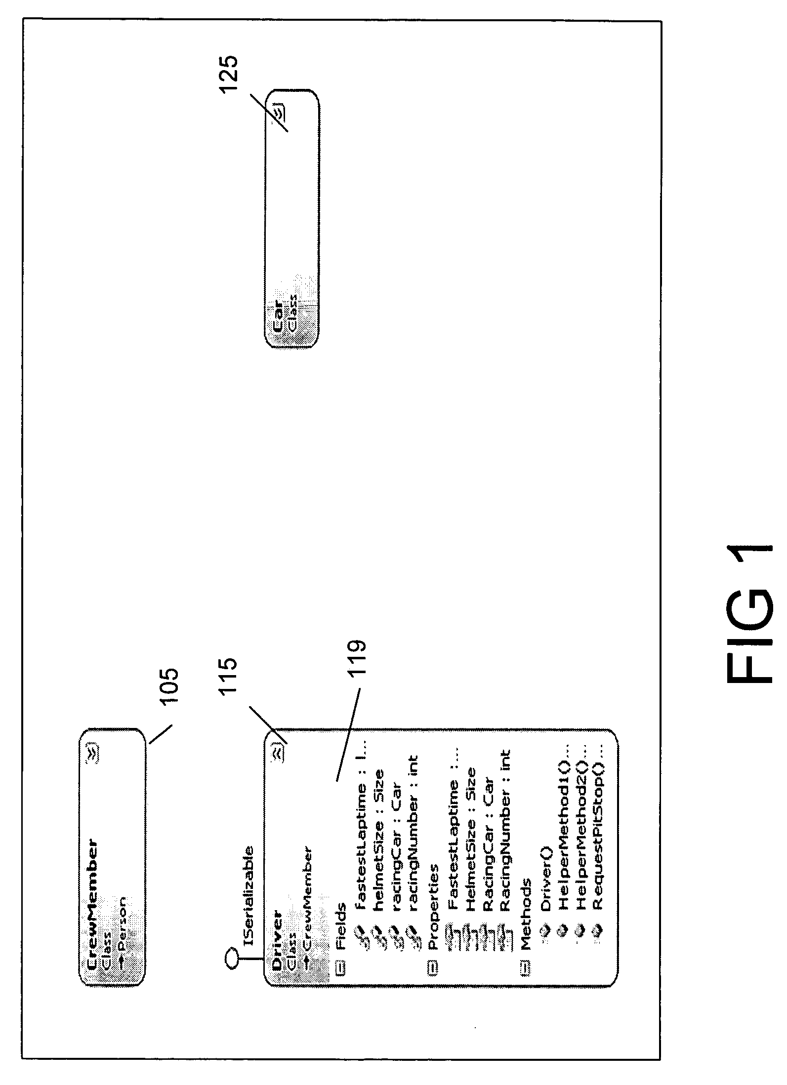
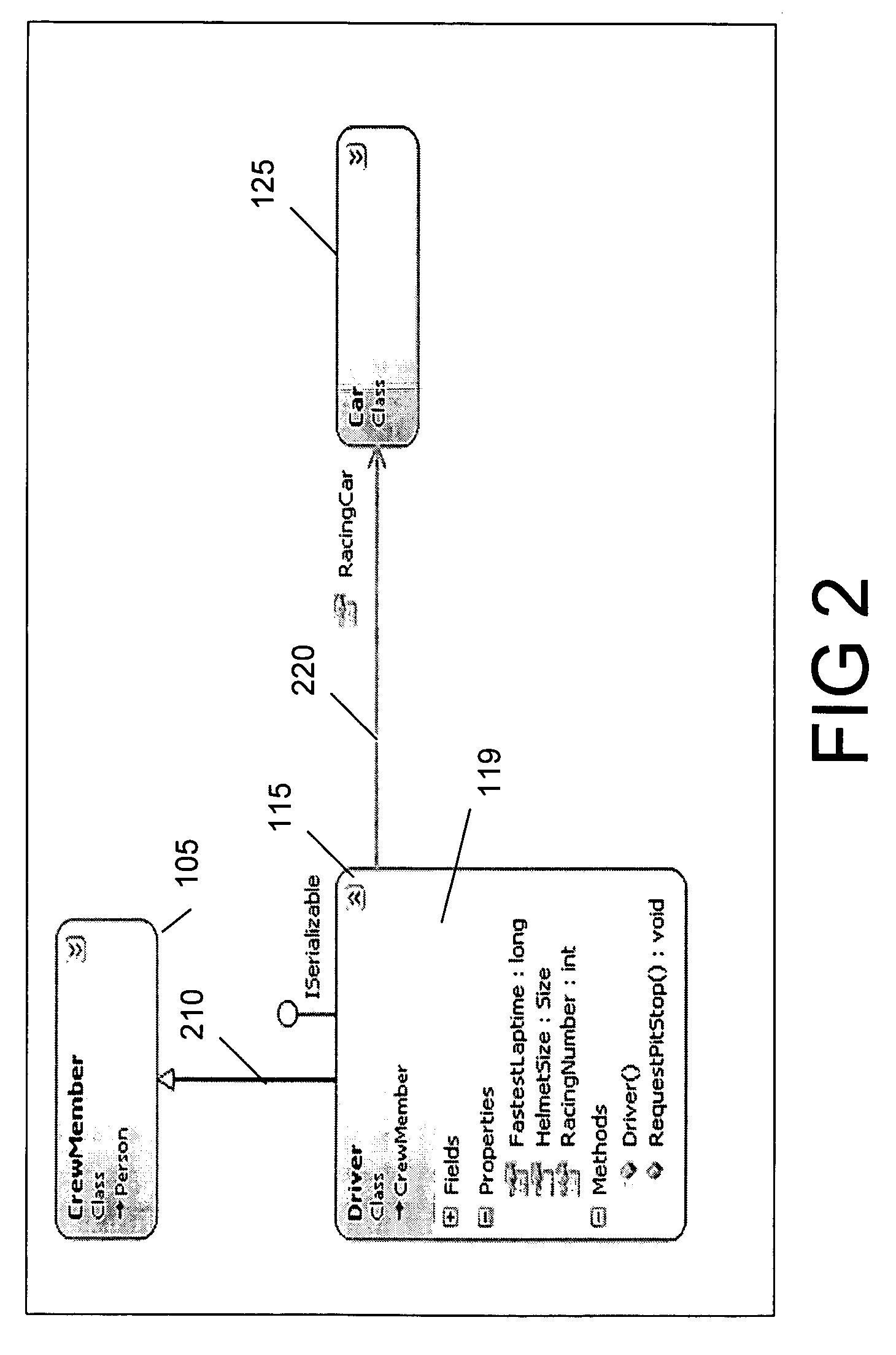
[0016]FIGS. 1, 2, 3 and 4 are exemplary screen shots of a software diagramming system in accordance with the present invention. A software diagram is a graphical representation of a software project. A software diagram comprises a plurality of shapes, as shown on FIG. 1 at 105, 115, and 125, for example. While the software diagrams are shown comprising three shapes, it is for illustrative purposes only, and not meant to limit the invention to diagrams comprising only three shapes. There is no limit to the number of shapes that can be supported by the present invention. In addition, the following description includes detail regarding software artifacts including classes and objects. The descriptions are for example only and not meant to limit the invention to the particular details or examples described.

[0017] Each of the shapes on the software diagram desirably correspond to software artifacts found in the associated software project. Software artifacts can comprise the inputs used...


PUM


Abstract

A software diagram is created based on software artifacts for a software program, where the software diagram comprises shapes corresponding to software artifacts. The diagram shapes may be customized to illustrate certain properties of the software artifacts or relationships between the software artifacts. Later, one or more changes are made to one or more of the software artifacts such that the diagram no longer accurately reflects the program code. A diagramming tool attempts to automatically update the software diagram to reflect the changed program code, but may be unable to account for at least one diagram shape because its associated software artifact has changed such that the diagramming tool no longer recognizes it as the same software artifact. The unaccounted for shape is known as an orphaned shape. A user may instruct the diagramming tool to associate the orphan shape with one of the changed software artifacts. The diagramming tool automatically reapplies the customizations previously associated with the orphan shape using the properties of the changed software artifact where applicable.

Description

FIELD OF THE INVENTION [0001] The invention relates to the field of modeling diagrams. More specifically, the invention relates to systems and methods for synchronizing concepts expressed on modeling diagrams with those of the underlying artifacts. BACKGROUND OF THE INVENTION [0002] Early software diagramming tools allowed users to draw diagrams that modeled abstract concepts such as objects, object inheritance, and data structures, to help design and describe complex object-oriented systems. Later, the addition of code structure generation features allowed users to take these models and generate software artifacts such as code stubs, header files, interface description files, and other code structures that the model represented. Further improvements of tools enabled users to go the other way and automatically generate diagrams from existing software artifacts. Often such graphical visualizations are useful for abstracting key details of a large collection of code structures, and th...

Claims


Application Information

Patent Timeline
Patent Type & Authority Applications(United States)
IPC IPC(8): G06F9/44
CPCG06F8/34
Inventor STALLO, GIOVANNIMERCER, JEREMY
Owner MICROSOFT TECH LICENSING LLC
Why Eureka
Try Eureka