
Bumper beam structure having support walls for center gusset, which are laid over walls of bumper beam

Inactive Publication Date: 2006-06-29
HONDA MOTOR CO LTD
View PDF9 Cites 8 Cited by
  • Summary
  • Abstract
  • Description
  • Claims
  • Application Information

AI Technical Summary

Benefits of technology

[0011] In light of the above circumstances, an object of the present invention is to provide a bumper beam structure which is reliably effective in various types of crashes, and by which when a pole crash occurs, the center gusset can reliably be crushed first without causing problems such as an increase in the weight of the vehicle.

Problems solved by technology

In the above bumper beam structure, when a pole crash occurs, the center gusset positioned at substantially the center of the bumper beam main body receives a load from a support pole or the like and is easily crushed.
In addition, such an increase in the thickness of the whole bumper beam main body causes an increase in a load for crushing a section of a side edge of the bumper beam main body.
Therefore, it is difficult to perform tuning for delaying buckling of a vehicle's side frame in comparison with the crushing of a section of the bumper beam main body when a high-speed offset crash occurs.

Method used


Image

  • Bumper beam structure having support walls for center gusset, which are laid over walls of bumper beam
  • Bumper beam structure having support walls for center gusset, which are laid over walls of bumper beam
  • Bumper beam structure having support walls for center gusset, which are laid over walls of bumper beam

Examples


Embodiment Construction

[0041] Hereinafter, an embodiment according to the present invention will be described with reference to FIGS. 1 to 7.

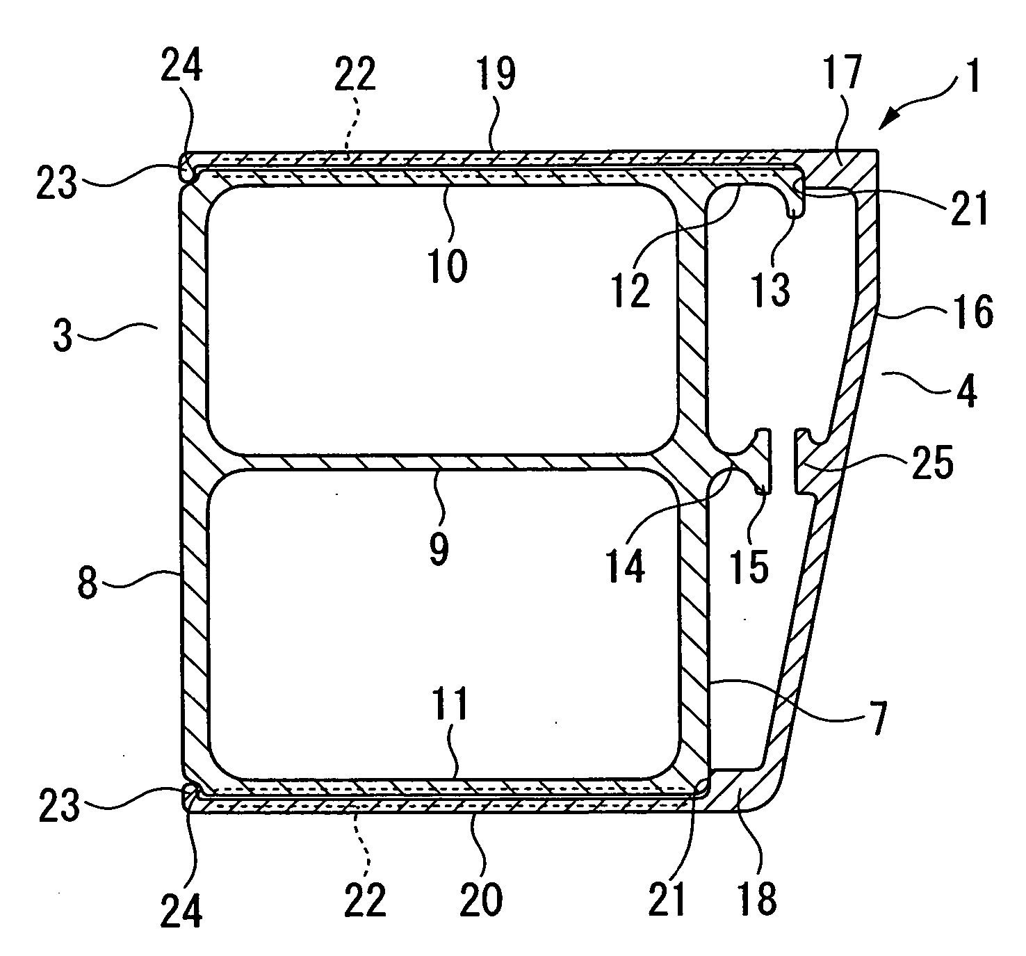
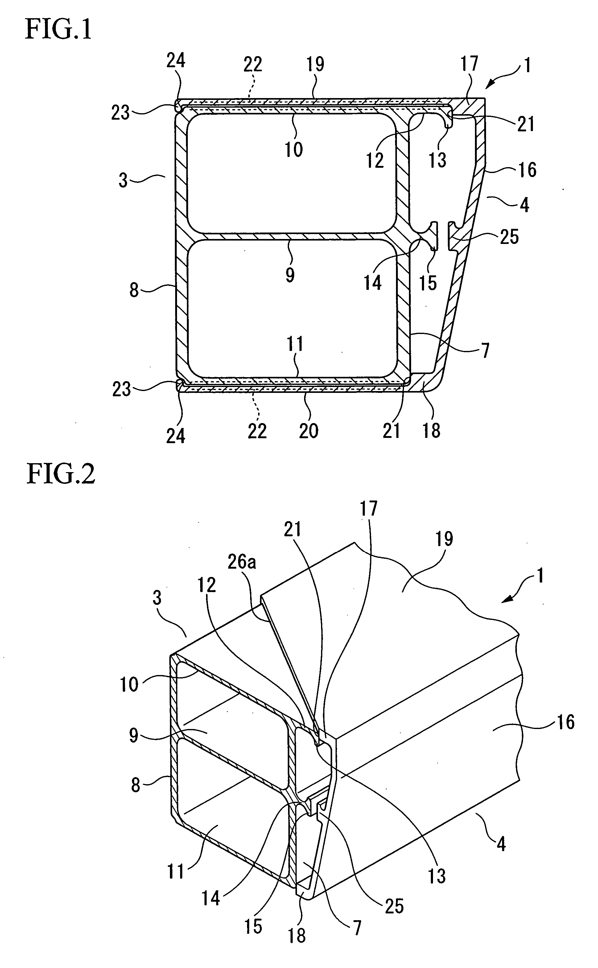
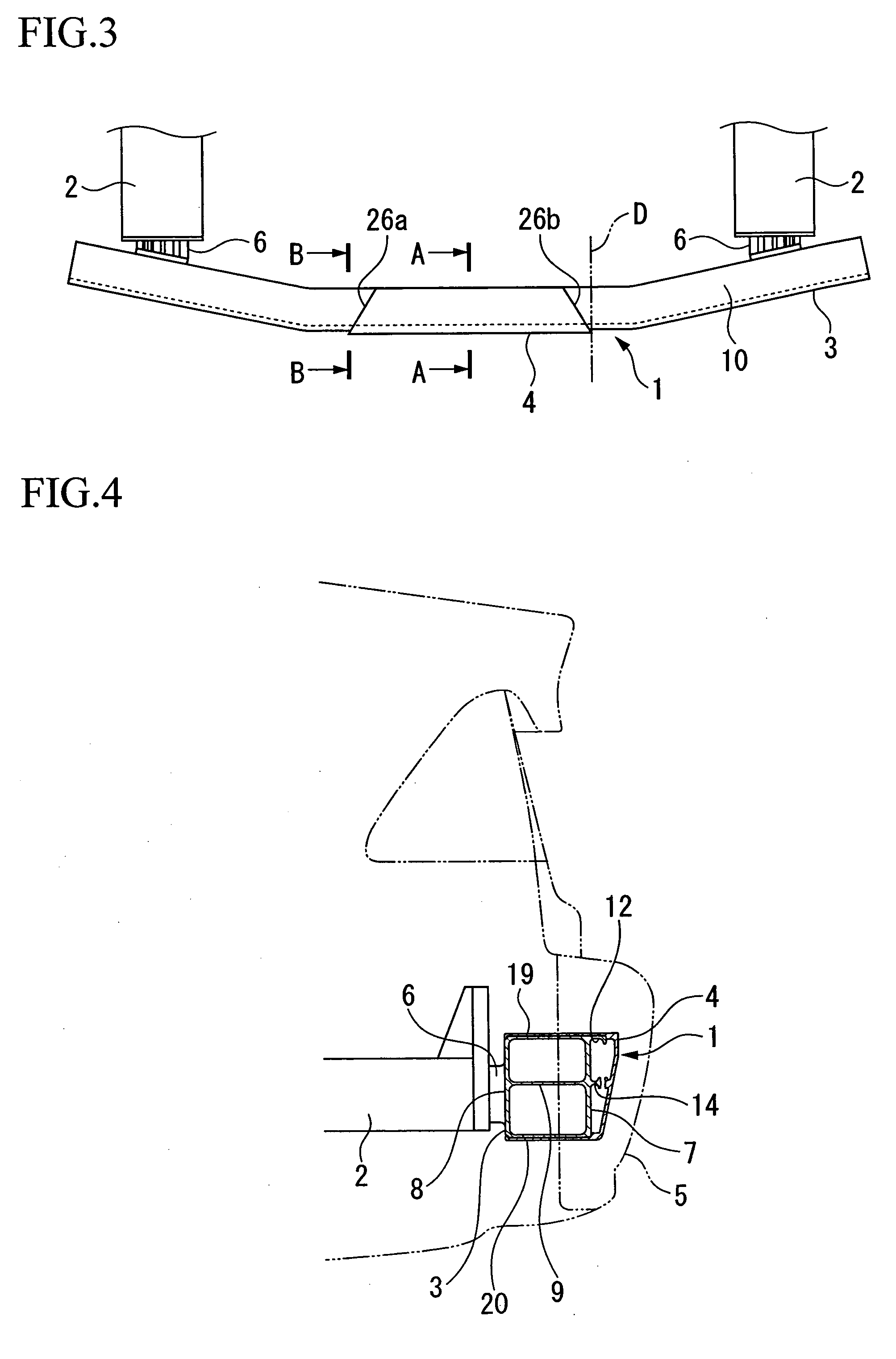
[0042]FIG. 3 is a plan view showing a frame portion of the back side of a vehicle body, to which a bumper beam structure of the present embodiment is attached. FIG. 4 is a sectional view along line A-A in FIG. 3. As shown in FIGS. 3 and 4, a bumper beam structure 1 of the present embodiment mainly consists of (i) a bumper beam main body 3 extending in a width direction of the vehicle body, wherein a rear face of the bumper beam main body 3 is joined to rear side frames 2 on either side of the vehicle body, and (ii) a center gusset 4 joined to substantially the center of the bumper beam main body 3 in the length direction thereof, wherein the center gusset 4 is attached to a front face side of the bumper beam main body 3. In addition, as shown in FIG. 4, a bumper face 5 can be attached to the bumper beam structure 1.

[0043] The bumper beam main body 3 is integrally f...


PUM


Abstract

A bumper beam structure has a metal and molded bumper beam main body extending in a width direction of a vehicle, wherein a rear face of the main body is joined to side frames of the vehicle; and a center gusset joined to a center portion of the bumper beam main body in the length direction of the main body so as to produce a closed section at a front face of the bumper beam main body. The center gusset has a pair of support walls which are respectively adhered and fastened to upper and lower walls of the bumper beam main body in a manner such that the support walls are respectively laid over the upper and the lower walls. Preferably, in each support wall, ends in a length direction of the support wall are inclined with respect to a plane which is perpendicular to the length direction.

Description

BACKGROUND OF THE INVENTION [0001] 1. Field of the Invention [0002] The present invention relates to a bumper beam structure which functions as a frame portion of a bumper of a vehicle. [0003] Priority is claimed on Japanese Patent Application No. 2004-372917, filed Dec. 24, 2004, the content of which is incorporated herein by reference. [0004] 2. Description of the Related Art [0005] In a bumper of a vehicle (i.e., a vehicle bumper), a bumper beam extending in a width direction of the vehicle is attached to ends of a pair of side frames, and a bumper face made of resin is attached to the front side of the bumper beam. [0006] Recently, a structure in consideration of a low-speed crash against a support pole or the like (called a “pole crash”, hereinbelow) is sometimes employed for the vehicle bumper. Such a vehicle bumper has a specific bumper beam structure for flexibly absorbing a load in a crash (see, for example, Japanese Unexamined Patent Application, First Publication No. H6-2...

Claims


Application Information

Patent Timeline
IPC IPC(8): B60R19/02
CPCB60R19/18B60R2019/1886
Inventor OKABE, KOJIROSHIOTSUKI, KATSUHIKOTSUICHIHARA, NOBUYUKIHAYASHI, NOBORU
Owner HONDA MOTOR CO LTD
Learn More