Adjustable torsion bar lever

a technology of torsion bar and lever, which is applied in the direction of torsion springs, loading/unloading vehicle arrangments, transportation items, etc., can solve the problems of vehicle not being able to return to the original specification for alignment, vehicle front end torsion bar sag, and torsion bar replacement at considerable cost, so as to increase the range of torsion, increase or decrease the ride height, and increase the road clearance

Active Publication Date: 2009-02-24
VERBOWSKI LARRY J
View PDF25 Cites 5 Cited by
  • Summary
  • Abstract
  • Description
  • Claims
  • Application Information

AI Technical Summary

Benefits of technology

[0010]An advantage of the present invention is to provide a two-piece adjustment lever for a torsion bar featuring an asymmetric spline arrangement within a fixed hex interface allowing for the torsion bar preload in a plurality of intermediate drive positions other than the first angular increments relative to the torsion bar at angular increments less than the degree increments in the hex interface. As a result, the torsion bar need not be replaced as its range of torsion is significantly increased.
[0011]Another advantage of the present invention is to provide the two-piece adjustable lever, which allows for increase or decrease in the ride height per owner preference, thereby increasing road clearance or providing custom vehicle appearance.
[0012]Still another advantage of the present invention is to provide the two-piece adjustable lever, which allows adjustment of the ride height to factory specification after the addition of vehicle accessories increases the sprung weight of the vehicle.
[0013]Still another advantage of the present invention is to provide the two-piece adjustment lever that is easily removed and calibrated to compensate for added load to the front of the vehicle and to compensate the torsion bar sag or fatigue.
[0014]The use of the present invention may allow maintenance of factory ride height to production specification for the life of the vehicle, without the necessity of replacing the torsion bar.

Problems solved by technology

Over time, the torsion bar has a tendency to relax or weaken, causing the front end of the vehicle to sag.
However, in many cases, the torsion bar has relaxed beyond the range of adjustment of the arm, such that the vehicle can no longer be brought back into the original specification for alignments.
Accordingly, the torsion bar must be replaced at considerable cost.
Many of these prior art designs are complex, bulky in structure and require considerable space under the vehicle body to allow the operator to adjust the systems.
Furthermore, at least some current designs require replacement of the relaxed torsion bar to restore a ride height due to insufficient adjustment travel in a production torsion bar adjustment lever.

Method used


Image

  • Adjustable torsion bar lever
  • Adjustable torsion bar lever
  • Adjustable torsion bar lever

Examples


Embodiment Construction

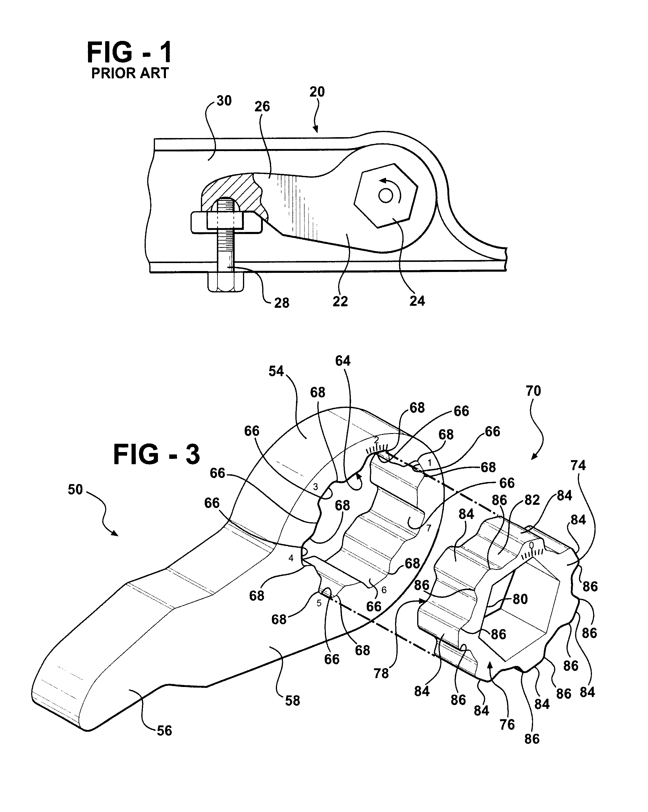
[0028]An adjustment lever assembly of the prior art is generally shown at 20 in FIG. 1. The prior art adjustment lever assembly 20 includes an adjustment lever 22 connected to a torsion bar 24. The adjustment lever 22 has an arm 26 that extends radially from the torsion bar 24 to be engaged by an adjustment bolt 28. The bolt 28 is carried on a vehicle frame 30 to raise or lower the position of the adjustment lever 22, i.e., pivot the lever 22 about the axis of the torsion bar 24. Over time, the torsion bar 24 has a tendency to relax, i.e., fatigue and loose torsional strength, thereby causing the front end of the vehicle (not shown) to sag. In many cases, the torsion bar 24 relaxes beyond the range of adjustment of the adjustment lever 22, such that the vehicle can no longer be brought back into original specification for alignments. In this case the torsion bar 24 must be replaced at considerable cost.

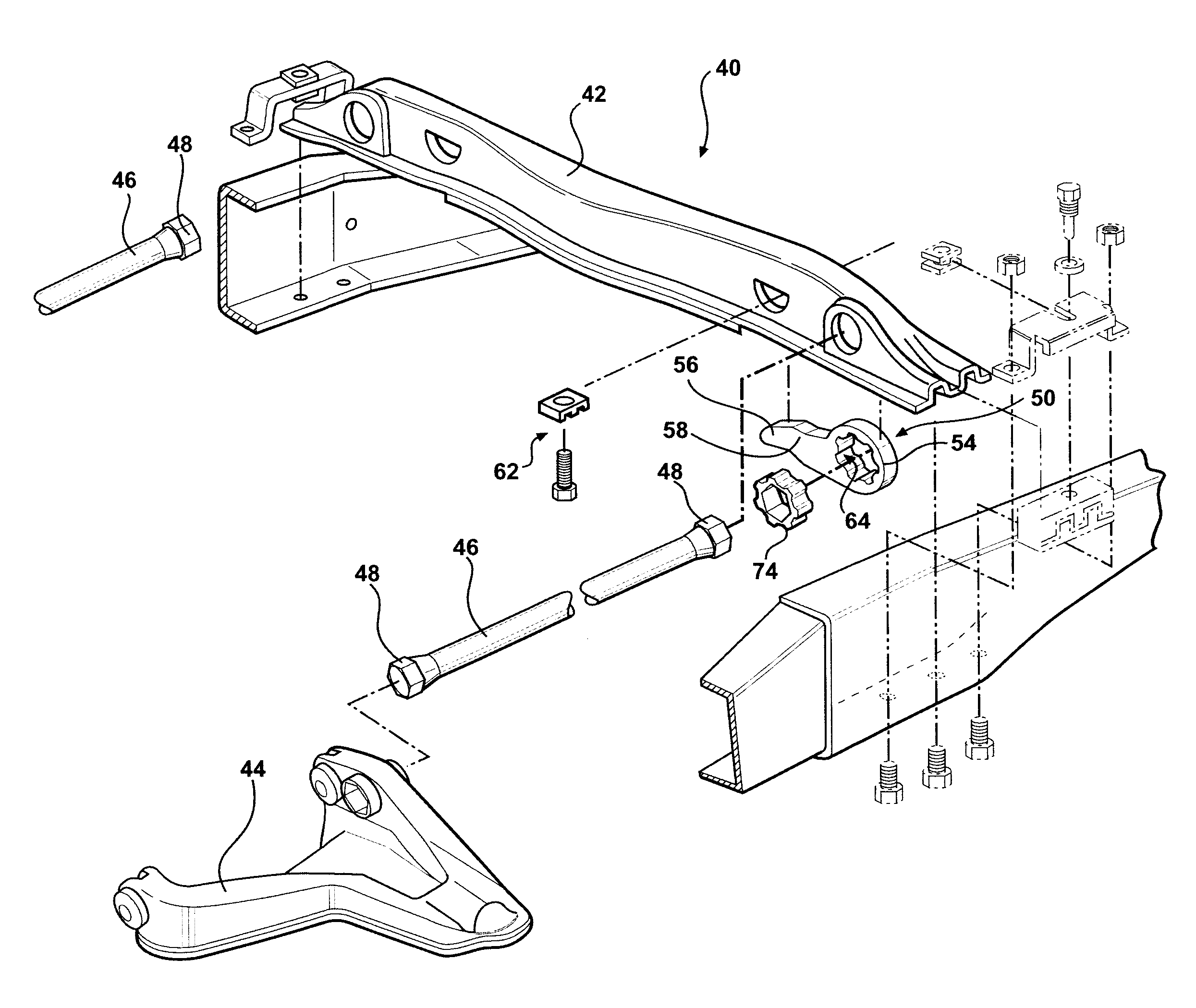
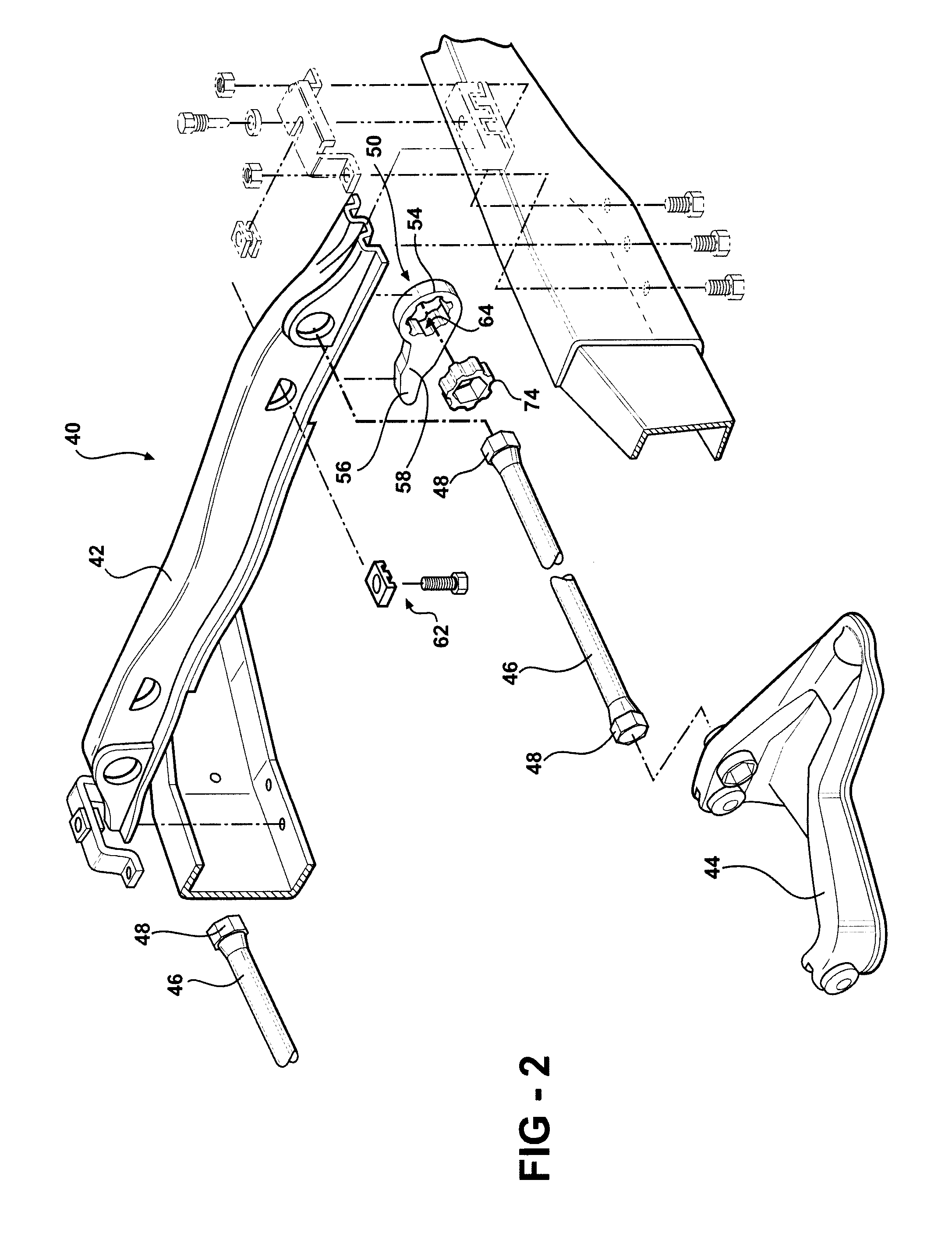
[0029]Referring to FIG. 2, an automobile vehicle suspension assembly is generally...


PUM


Abstract

A suspension assembly (40) in an automobile vehicle includes a support frame (42), a control arm (44) movable relative to the support frame (42), and a torsion bar (46) connected to the control arm (44) for resisting movement of the control arm (44). An adjustment lever (50, 150, 250, 350, 450, 550, 650) is connected to the torsion bar (46) for placing the torsion bar (46) in torsion. A hub (74, 174, 274, 374, 474, 574, 674) is positioned in a socket in the adjustment lever (50, 150, 250, 350, 450, 550, 650) for connecting the adjustment lever (50, 150, 250, 350, 450, 550, 650) to the torsion bar (46) at a plurality of primary drive positions at first angular increments as defined by a hexagonal connection. The hub (74, 174, 274, 374, 474, 574, 674) is connected to the adjustment lever (50, 150, 250, 350, 450, 550, 650) by an indexing system to allow positioning of the adjustment lever (50, 150, 250, 350, 450, 550, 650) at a plurality of intermediate drive positions other than the first angular increments defined by the hexagonal connection to the torsion bar (46).

Description

RELATED APPLICATION[0001]The subject patent application claims priority to and all the benefits of the U.S. Provisional Patent Application Ser. No. 60 / 465,254 filed on Apr. 24, 2003.BACKGROUND OF THE INVENTION[0002]1. Field of the Invention[0003]The subject invention relates to a suspension assembly for an automotive vehicle, and more particularly to a torsion bar suspension system and an adjustment lever for adjusting the torsion in the torsion bar.[0004]2. Description of the Prior Art[0005]A torsion bar suspension system of the type having a suspension height adjusting mechanism is well known in the art and is widely used in an automotive industry today. Such a torsion bar suspension system includes a lower control arm having a typical A-frame construction that mounts the torsion bar at its legs and mounts upper and lower ball joints at its opposite end. A torsion bar adjustment arm, i.e. a lever, is mounted on the torsion bar and has an arm that extends radially from the torsion ...

Claims


Application Information

Patent Timeline
Patent Type & Authority Patents(United States)
IPC IPC(8): B60G11/18B60G11/20F16F1/16
CPCB60G11/20F16F1/16B60G2204/1224B60G2204/61
Inventor VERBOWSKI, LARRY J.
Owner VERBOWSKI LARRY J
Why Eureka
Try Eureka