Threaded connection

a threaded connection and thread technology, applied in the direction of screw threaded joints, mechanical equipment, drilling pipes, etc., can solve the problems of insufficient sealability and inability to exhibit the appropriate sealability, and achieve the effect of widening the torque rang

Active Publication Date: 2021-10-19
VALLOUREC OIL & GAS FRANCE SAS
View PDF33 Cites 0 Cited by
  • Summary
  • Abstract
  • Description
  • Claims
  • Application Information

AI Technical Summary

Benefits of technology

[0006]In view of this, for example, a threaded connection that requires high torque, as that of Patent Document 1, is designed to exhibit the appropriate sealability when made up with high torque. If such a threaded connection is made up with low torque, it will not exhibit the appropriate sealability. Further, in the case of a trapezoidal thread form such as that of WO2015 / 083382 A1, when the connection is made up with high torque, forces are applied to the male and female threads in such directions that they are separated from each other, and thus they can be easily disengaged.
[0009]The threaded connections according to embodiments widen the torque range in which a predetermined performance is achieved. This will achieve a wider range of applications of the threaded connections.

Problems solved by technology

That is, if a torque exceeding the appropriate range is applied, this may impair sealability.
If such a threaded connection is made up with low torque, it will not exhibit the appropriate sealability.

Method used


Image

  • Threaded connection
  • Threaded connection
  • Threaded connection

Examples


embodiment 1

[0092][Embodiment 1]

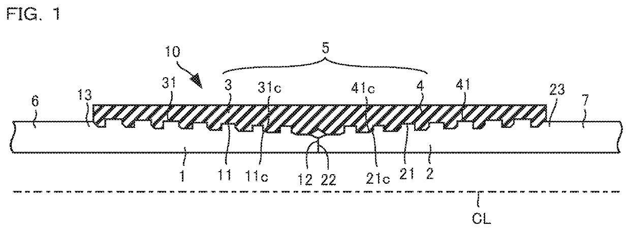
[0093]FIG. 1 is a longitudinal cross-sectional view of a threaded connection according to Embodiment 1. FIG. 1 shows a portion of the longitudinal cross-sectional view of the connection of a pair of pipes that is located higher than the pipe axis CL; in reality, a mirror image of the longitudinal cross-sectional view shown in FIG. 1 with respect to the pipe axis CL is present below the pipe axis CL.

[0094]Referring to FIG. 1, the threaded connection 10 according to Embodiment 1 includes pins 1 and 2 and boxes 3 and 4.

[0095]The threaded connection 10 is a coupling-type threaded connection.

[0096]The pins 1 and 2 are provided on pipe ends of a pair of pipes 6 and 7 that are connected to each other.

[0097]The boxes 3 and 4 are provided on the ends, as determined along the pipe-axis CL direction, of a coupling 5 connecting the pipes 6 and 7.

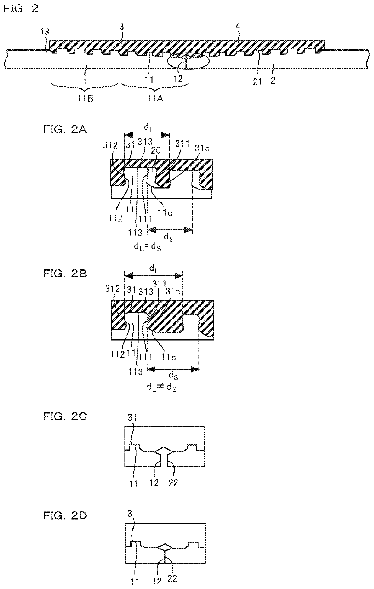
[0098]The pin 1 includes, starting with the tip of the pipe 6 onward, a shoulder 12 and a male thread 11. The shoulder 12 is locate...

embodiment 2

[0207][Embodiment 2]

[0208]FIG. 10 is a longitudinal cross-sectional view of a threaded connection according to Embodiment 2. FIG. 10 shows a portion of the longitudinal cross-sectional view of the connection of a pair of pipes that is located higher than the pipe axis CL; in reality, a mirror image of the longitudinal cross-sectional view shown in FIG. 10 with respect to the pipe axis CL is present below the pipe axis CL.

[0209]Referring to FIG. 10, the threaded connection 100 according to Embodiment 2 includes pins 1 and 2 and boxes 3D and 4D.

[0210]The threaded connection 100 is a coupling-type threaded connection.

[0211]The pins 1 and 2 are as described above.

[0212]The box 3D is provided on one end of a coupling 5D that connects a pair of pipes 6 and 7, and the box 4D is provided on the other end of the coupling 5D.

[0213]The box 3D has a construction obtained by adding a shoulder 34 to the box 3. The box 4D has a construction obtained by adding a shoulder 44 to the box 4.

[0214]The s...

embodiment 3

[0261][Embodiment 3]

[0262]FIG. 14 is a longitudinal cross-sectional view of a threaded connection according to Embodiment 3. FIG. 14 shows a portion of the longitudinal cross-sectional view of the connection of a pair of pipes that is located higher than the pipe axis CL; in reality, a mirror image of the longitudinal cross-sectional view shown in FIG. 14 with respect to the pipe axis CL is present below the pipe axis CL.

[0263]Referring to FIG. 14, the threaded connection 200 according to Embodiment 3 includes pins 201 and 202 and boxes 203 and 204.

[0264]A pair of pipes 210 and 220 are to be connected, and the pin 201 is provided on a pipe end of one pipe 210.

[0265]The pin 202 is provided on a pipe end of the other pipe 220.

[0266]The box 203 is provided on one end of a coupling 205 that connects the pipes 210 and 220, while the box 204 is provided on the other end of the coupling 205.

[0267]The pin 201 includes a male thread 211, an intermediate shoulder 213 and a male thread 212, in...


PUM


Abstract

A threaded connection includes a pin including a wedge male thread having a varying-thread-width portion and a box including a wedge female thread having a varying-thread-width portion. The threaded connection is constructed such that, when both stab flanks and load flanks of the male thread of the pin contact the box, the shoulder on the pin is not in contact with the shoulder on the pin, and, with a further rotation in the make-up direction, the shoulder on the pin is capable of contacting the shoulder on the pin before the threads (i.e. male and female threads) yield.

Description

RELATED APPLICATION DATA[0001]This application is a National Stage Application under 35 U.S.C. 371 of co-pending PCT application number PCT / JP2017 / 033565 designating the United States and filed Sep. 15, 2017; which claims the benefit of JP application number 2016-181175 and filed Sep. 16, 2016 each of which are hereby incorporated by reference in their entireties.TECHNICAL FIELD[0002]The present invention relates to a threaded connection.BACKGROUND ART[0003]In an oil well, a natural gas well, etc. (hereinafter also collectively referred to as “oil well”), an oil-well pipe, such as casing or tubing, that is used is a series of steel pipes connected with each other by means of threaded connections.[0004]In recent years, especially in shale wells, mining by horizontal digging has become widespread to improve production efficiency. A threaded connection for oil-well pipes used in such applications is required to have high torque. To increase the torque performance of a threaded connecti...

Claims


Application Information

Patent Timeline
Patent Type & Authority Patents(United States)
IPC IPC(8): F16L15/00F16L15/04E21B17/042
CPCF16L15/04E21B17/042F16L15/002
Inventor MARUTA, SATOSHIIWAMOTO, MICHIHIKO
Owner VALLOUREC OIL & GAS FRANCE SAS
Why Eureka
Try Eureka