Diaphragm coupling

A diaphragm coupling and coupling technology, applied in the direction of couplings, elastic couplings, mechanical equipment, etc., can solve the problems of inconvenient installation and complicated processing of couplings, and achieve convenient assembly and disassembly, tolerances Low demand, the effect of increasing the torque range

Inactive Publication Date: 2018-01-09
天津华美佳业仿真花卉有限公司
View PDF0 Cites 0 Cited by
  • Summary
  • Abstract
  • Description
  • Claims
  • Application Information

AI Technical Summary

Problems solved by technology

At present, the existing technology discloses a coupling that adopts a completely separate coupling body and coupling. This coupling is not easy to install, and the processing is relatively complicated, so it is necessary to improve it.

Method used


Image

  • Diaphragm coupling

Examples


Embodiment Construction

[0011] Below, the substantive features and advantages of the present invention will be further described in conjunction with examples, but the present invention is not limited to the listed examples.

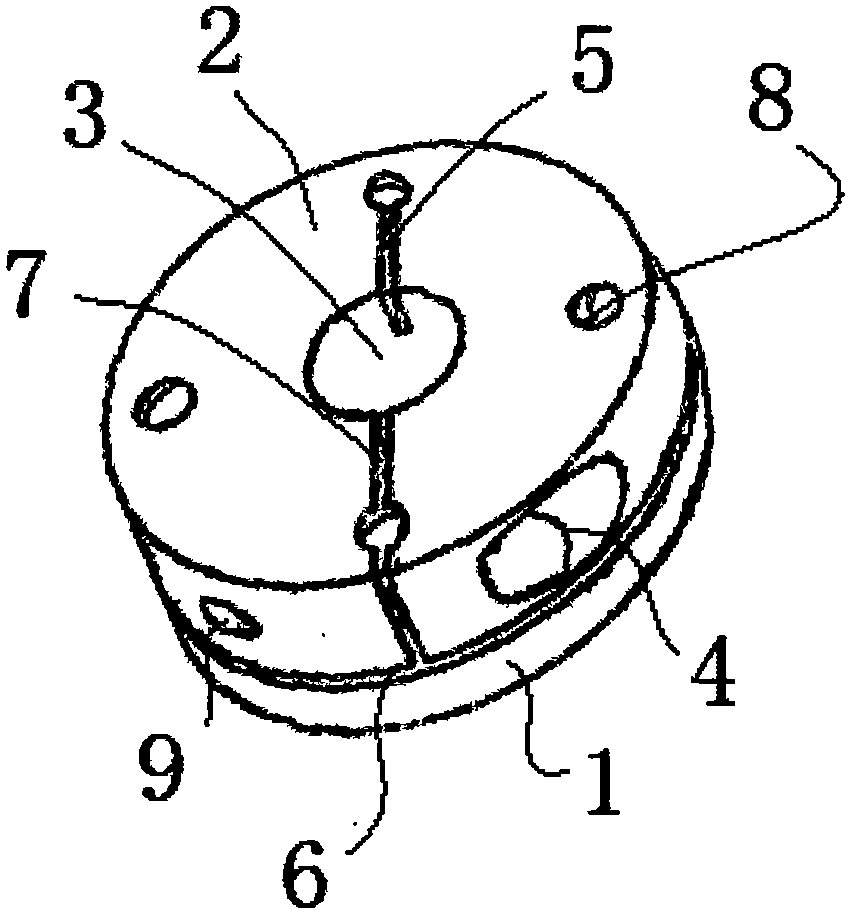
[0012] See figure 1 , a diaphragm coupling, including a coupling body 1 and a connecting body 2, a radial slit 6 is arranged between the coupling body and the connecting body, and the connecting body is outward from the center of the shaft hole 3 A first axial slit 7 and a second axial slit 5 are provided, the first axial slit and the second axial slit are on a straight line, and the connecting body and the axial end surface of the coupling body Four diaphragm fixing bolt holes 8 are evenly arranged in a cross shape, two of which are located on the centerlines of the first axial slit and the second axial slit, and the first axial slit 7 Leading to the outer circular surface of the connecting body 2 and communicating with the radial slit 6, the outer end of the second axial slit...


PUM


Abstract

The invention relates to a diaphragm coupling, comprising a coupling body and a connecting body, a radial slit is arranged between the coupling body and the connecting body, and a radial seam is arranged on the connecting body from the center of the shaft hole to the outside. The first axial slit and the second axial slit, the first axial slit and the second axial slit are on a straight line, the connecting body and the axial end surface of the coupling body are cross-shaped, The connecting body and the axial end surface of the coupling body are provided with four diaphragm fixing bolt holes, two of which are located in the center of the first axial slit and the second axial slit On the line, the first axial slit leads to the outer circular surface of the connecting body and communicates with the radial slit, and the outer end of the second axial slit ends at the corresponding diaphragm fixing bolt hole, And the second axial slit is not connected to the radial slit. The diaphragm coupling of the present invention adopts a semi-separated structure and a bolt connection structure, which effectively increases the torque range of the diaphragm coupling, is convenient to assemble and disassemble, and is more suitable for lengthening the shaft coupling.

Description

technical field [0001] The invention belongs to the technical field of shaft couplings, in particular to a diaphragm shaft coupling. Background technique [0002] A coupling is a mechanical part used to connect two shafts in different mechanisms: the driving shaft and the driven shaft, so that they rotate together to transmit torque. The two shafts cannot be separated when the machine is running, and the two shafts can only be separated after the machine is parked and the connection is disassembled. In high-speed and heavy-duty power transmission, some couplings also have the functions of buffering, damping and improving the dynamic performance of the shafting. The coupling consists of two halves, which are respectively connected to the driving shaft and the driven shaft. Generally, the power machine is mostly connected with the working machine by means of a coupling. Generally, the power machine is mostly connected with the working machine by means of a coupling, which i...

Claims


Application Information

Patent Timeline
Patent Type & Authority Applications(China)
IPC IPC(8): F16D3/56
Inventor 郑朝京
Owner 天津华美佳业仿真花卉有限公司
Why Eureka
Try Eureka