Cutter with novel port

An interface and tool technology, applied in the field of tools with new interfaces, can solve the problems of many layers that cannot be superimposed, poor dynamic balance, cutting vibration, etc., to simplify dynamic balance calibration, reduce maintenance costs, and prevent wear and deformation. Effect

Pending Publication Date: 2020-04-10
杭州希恩希拓斯精密机械有限公司
View PDF3 Cites 0 Cited by
  • Summary
  • Abstract
  • Description
  • Claims
  • Application Information

AI Technical Summary

Problems solved by technology

This form of interface has the following disadvantages: 1. The angular displacement of the cutter head and the cutter body is relatively large. If the contact point is worn, the angular displacement will continue to increase, and the cutting force cannot be controlled as expected.
2. Single direction is valid, only used for the tool with the spindle rotating in the forward direction or the tool with the spindle in the reverse direction
3. The dynamic balance is not good, and a hole is opened on the whole circle, so that the balance effect on the circle is not good, it is not suitable for high-speed cutting, and vibration may occur during cutting
4. The versatility is not good, this interface can only be used for this type of tool, other tools are not suitable
Theoretically, as long as the central screw is long enough, this structure can stack the cutter sets infinitely, so that the cutting length of the cutter will increase, but in reality, it will be unstable due to the layer-by-layer stacking and the positioning pin of the uppermost cutter set must bear a very large torque, thus Doomed not to stack too many layers
3. The tool does not conform to the principle of dynamic balance design
4. Poor versatility
5. The distribution of the blades on the circumference is too concentrated in some places, and the gap in some places is too large, which will lead to sudden force and sudden withdrawal of force during cutting, which is prone to cutting vibration
6. The knife set at the bottom has two pin holes open to the outside, where chips, dust, oil, etc. are easy to enter, and may also cause wind noise
[0007] The Chinese utility model patent with the notification number CN208945257U discloses an extended corn milling cutter, which uses a cylinder for centering and has the following disadvantages: 1. Only rely on the cylinder for centering and a gasket to lock after installation, and the cutter head and the cutter The torque between the bodies only depends on the friction force after the screw is pressed. This tool can withstand even worse torque and cannot perform heavy cutting
2. There is only cylinder centering, no torque drive device, and cannot be positioned on the circumference. The angular position of the cutter head and the cutter body on the circumference cannot be controlled during installation, and the cutting control expected by the design cannot be achieved.

Method used


Image

  • Cutter with novel port
  • Cutter with novel port
  • Cutter with novel port

Examples


Embodiment 1

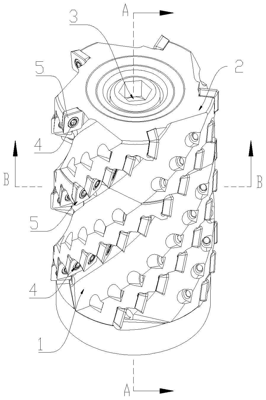
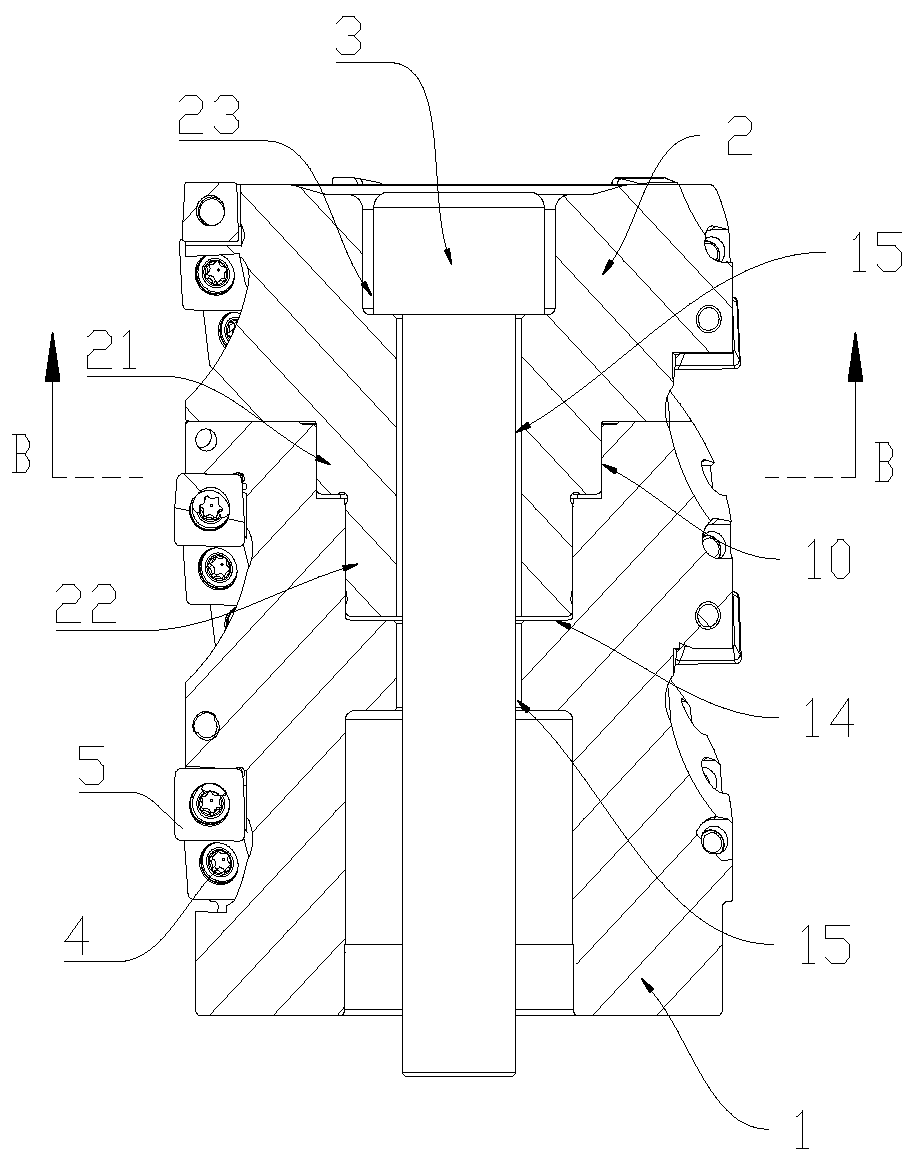
[0033] Figure 1 to Figure 7 A tool with a novel interface according to an embodiment of the invention is schematically shown. As shown in the figure, the device includes a cutter body 1 , a cutter head 2 , a bolt 3 , a plurality of blades 5 and a plurality of screws 4 . Wherein, a plurality of blades 5 are fixed on the side of the cutter head 2 or the cutter body 1 by screws 4 . The cutter body 1 is arranged opposite to the cutter head 2 , and the central axes of the cutter body 1 and the cutter head 2 are both provided with bolt through holes 15 . The top end surface of the cutter head 2 is provided with a screw counterbore 23 . The diameter of the screw counterbore 23 is larger than the diameter of the bolt through hole 15 , and the screw counterbore 23 and the bolt through hole 15 are arranged concentrically.

[0034] Such as figure 2 and Figure 4 As shown, the cutter body 1 is provided with a double counterbore structure, and the double counterbore structure includ...

Embodiment 2

[0045] The cutter with novel interface in this embodiment differs from Embodiment 1 in the following points:

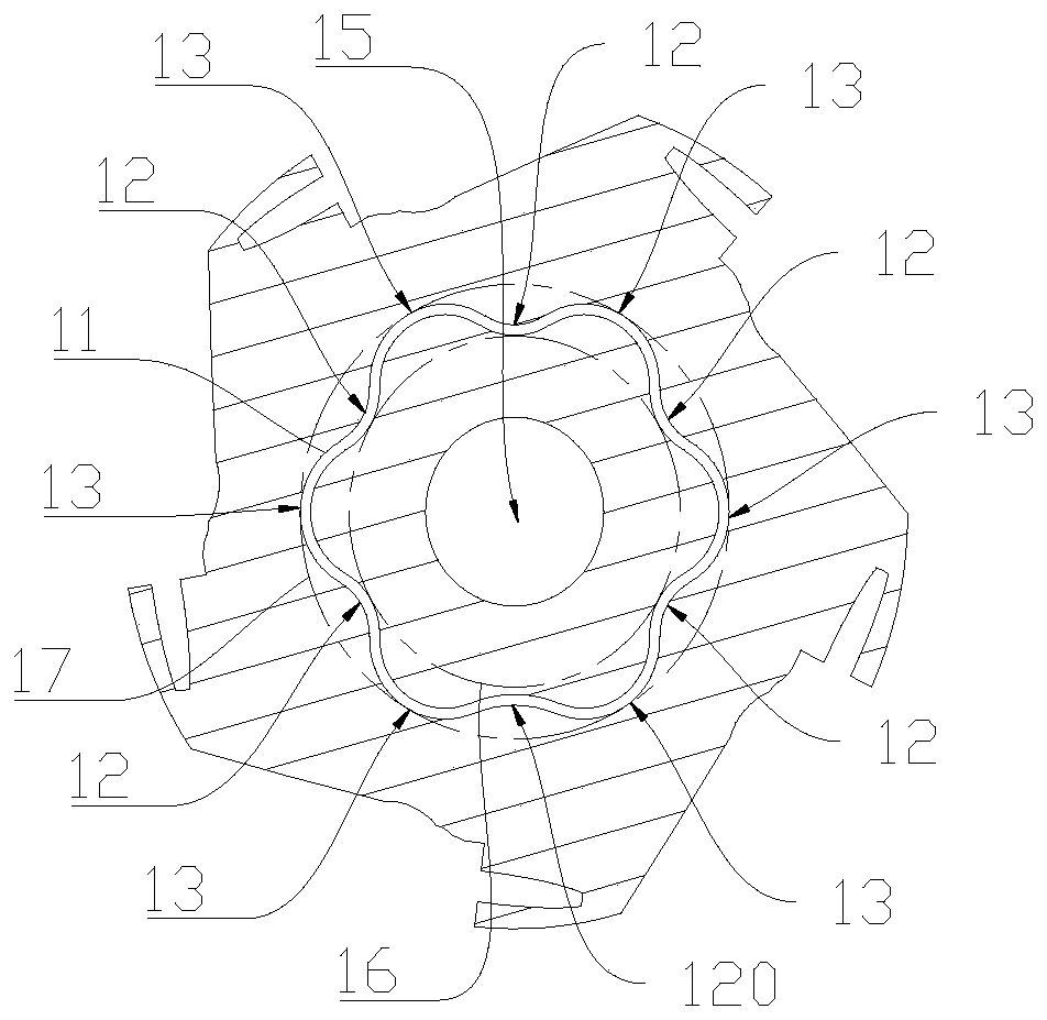
[0046] The closed curve 11 obtained by the axial projection of the torque-driven boss 21 and the torque-driven counterbore 10 from the bottom of the cutter body 1 is a six-petal quincunx shape, such as Figure 7 (f) shown. The multi-segment arcs forming the closed curve 11 include 6 convex arcs 13 with equal radii and lengths, and 6 concave arcs 12 with equal lengths. The 6 concave arcs 12 correspond to the inscribed circle 16 tangent, the 6 convex arcs 13 are tangent to the circumscribed circle 17. The mating surfaces of the torque-driven boss 21 and the torque-driven counterbore 10 form a multi-angle symmetrical form. When cutting with a tool, the mating surfaces of the torque-driven boss 21 and the torque-driven counterbore 10 are evenly stressed, which can effectively prevent tool deformation , deflection. In addition, the radii of the six convex arcs 13 are sm...


PUM


Abstract

The invention discloses a cutter with a novel port. The cutter comprises a cutter body and a cutter head which are connected through a bolt, wherein a blade is connected to the cutter head; the cutterbody is in clearance fit with the cutter head through a bicylinder port; the bicylinder port comprises a dual countersunk structure located at one end of the cutter body and a dual boss structure located at one end of the cutter head; and the matching surfaces of the dual countersunk structure and the dual boss structure are multi-section curve surfaces. According to the cutter disclosed by the invention, centering is performed through the guidance of a bicylinder, so that the concentricity of the cutter body and the cutter head is guaranteed; torque is transmitted by the port through the multi-section curve surfaces, so that the torque scope which can be borne by the port can be substantially increased, and the dynamic balance effect is good; the bicylinder port is adopted, so that the cutter can rotate positively or negatively, and the application range is more extensive; and in addition, the cutter disclosed by the invention is good in port hiding performance, so that when the cutter is used, the port is not liable to be influenced by outside, and the maintenance cost is reduced.

Description

technical field [0001] The invention relates to the field of cutting tools, in particular to a cutting tool with a new interface. Background technique [0002] At present, the field of metal cutting processing is developing rapidly, and indexable tools are widely used. The biggest advantage of using indexable tools is that the cost of tools is lower. This is mainly because indexable tools are mostly designed by modularization. This type of blade can be used in a variety of cutter bodies, and a kind of cutter body can be combined with a variety of tool handles through a series of standard interfaces, making the tool versatile and easy to promote. [0003] Looking at all kinds of tool interfaces on the market, most of them are developed abroad, and there are very few interfaces independently developed by my country and widely promoted. The main reason is that the standards are too low and the technology is not mature enough. [0004] Taking the long-blade square shoulder mill...

Claims


Application Information

Patent Timeline
Patent Type & Authority Applications(China)
IPC IPC(8): B23C5/10B23C5/20
CPCB23C5/109B23C5/20
Inventor 何吉孙东周
Owner 杭州希恩希拓斯精密机械有限公司
Why Eureka
Try Eureka