
Light emitting diode arrays for direct backlighting of liquid crystal displays

a technology of light-emitting diodes and liquid crystal displays, which is applied in the direction of lighting device details, lighting and heating apparatuses, instruments, etc., can solve the problems of increasing the thickness of the lcd display, affecting the efficiency of the edge lighting, and affecting the efficiency of the backlighting effect of the display

Active Publication Date: 2006-06-29
BRIGHTPLUS VENTURES LLC
View PDF99 Cites 49 Cited by
  • Summary
  • Abstract
  • Description
  • Claims
  • Application Information

AI Technical Summary

Benefits of technology

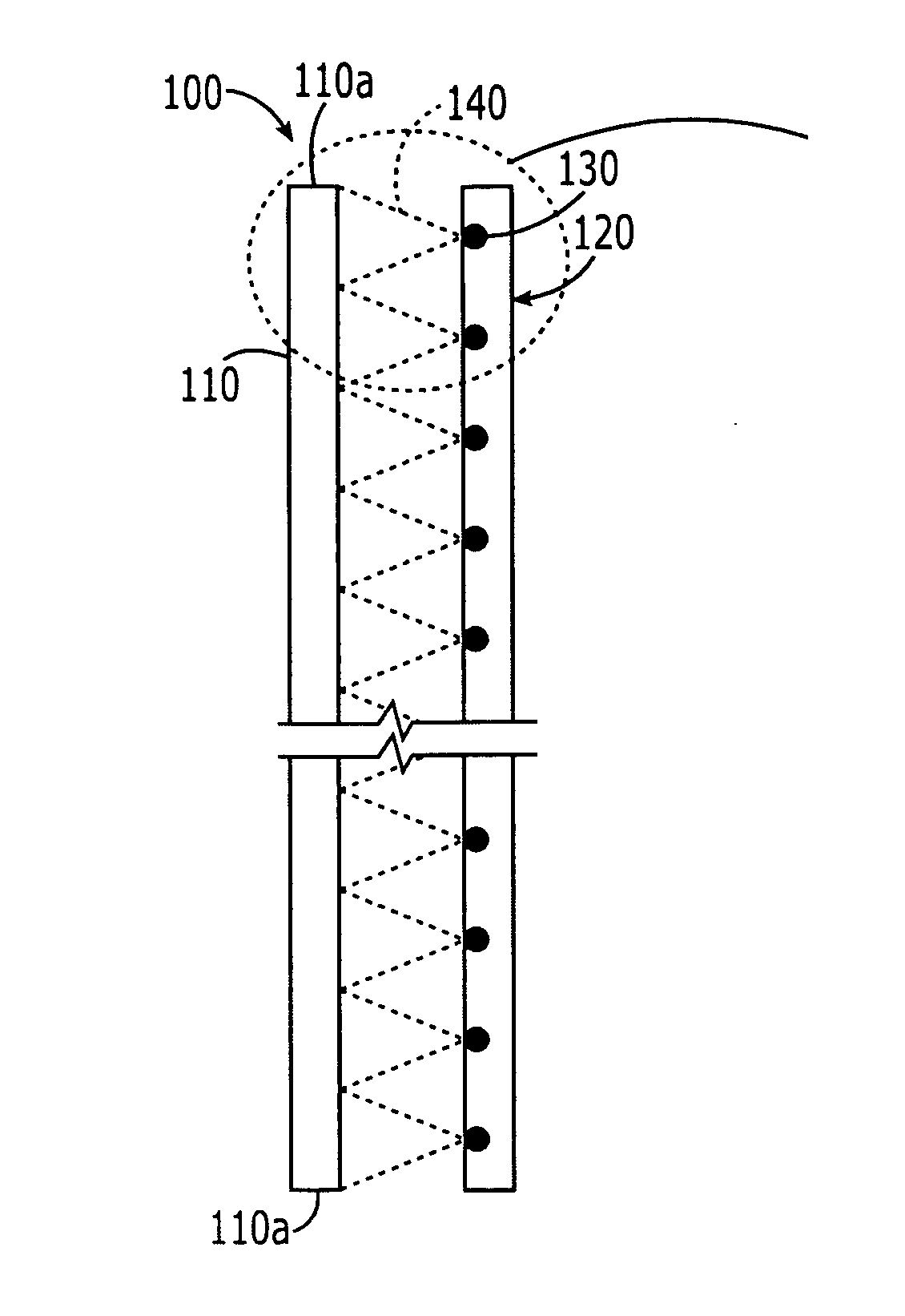
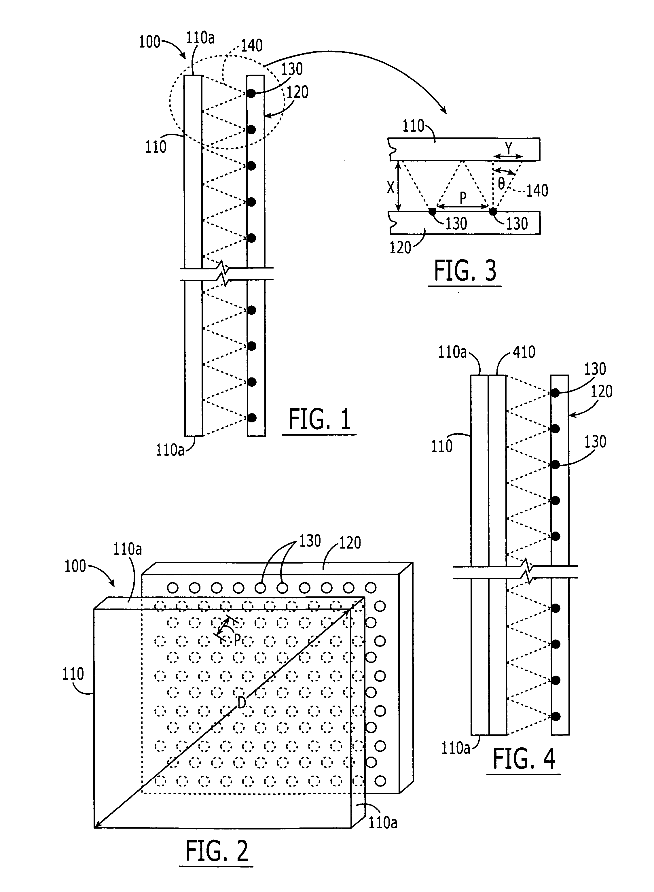
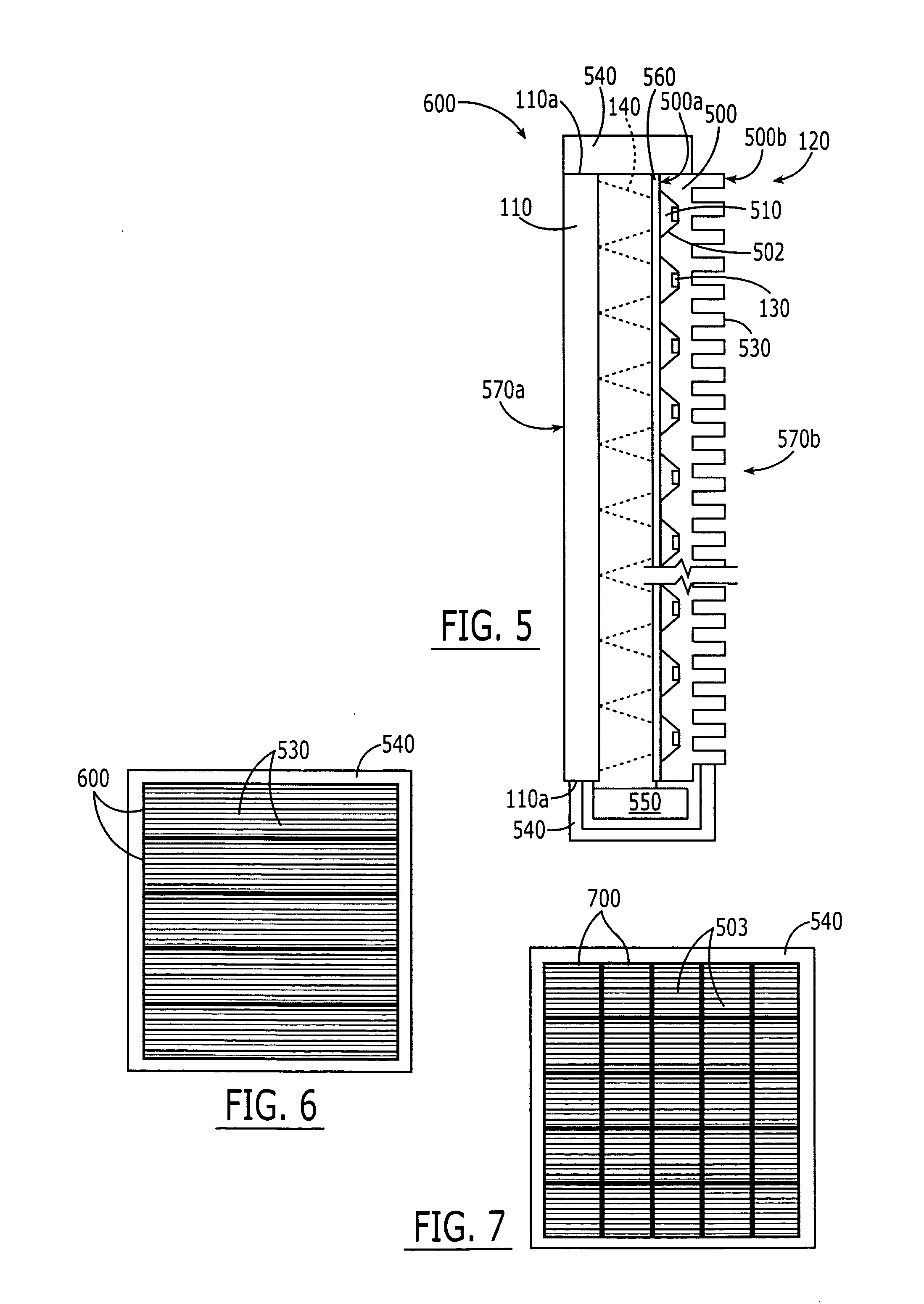
"The present invention provides a display panel for a flat panel display that includes a planar array of LCD devices and a planar array of LED devices that is close enough to provide uniform backlighting for the LCD devices. The LED devices can be arranged in a variety of ways, such as a single solid metal block or multiple solid metal blocks, and can include reflector cavities and heat sink fins. The LED devices can emit light that appears as white light or at different frequencies. The invention also provides a flat panel display with a front face comprising a planar array of LCD devices and a back face comprising at least one solid metal block that includes reflector cavities and heat sink fins. A frame can be provided to surround the front and back faces of the flat panel display. The technical effects of the invention include improved backlighting and reduced power consumption."

Problems solved by technology

Unfortunately, such edge lighting may be inefficient, with up to 50% or more of the light being lost.
Unfortunately, an array of fluorescent cold cathode tubes may increase the thickness of the LCD display and / or increase the power consumption thereof.
It also may be difficult to uniformly illuminate the planar array of LCD devices with the array of fluorescent cold cathode tubes.

Method used


Image

  • Light emitting diode arrays for direct backlighting of liquid crystal displays
  • Light emitting diode arrays for direct backlighting of liquid crystal displays
  • Light emitting diode arrays for direct backlighting of liquid crystal displays

Examples


Embodiment Construction

[0022] The present invention now will be described more fully hereinafter with reference to the accompanying drawings, in which embodiments of the invention are shown. However, this invention should not be construed as limited to the embodiments set forth herein. Rather, these embodiments are provided so that this disclosure will be thorough and complete, and will fully convey the scope of the invention to those skilled in the art. In the drawings, the thickness of layers and regions are exaggerated for clarity. Like numbers refer to like elements throughout. As used herein the term “and / or” includes any and all combinations of one or more of the associated listed items and may be abbreviated as “ / ”.

[0023] The terminology used herein is for the purpose of describing particular embodiments only and is not intended to be limiting of the invention. As used herein, the singular forms “a”, “an” and “the” are intended to include the plural forms as well, unless the context clearly indica...


PUM


Abstract

A display panel for a flat panel display includes a planar array of LCD devices and a planar array of LED devices that is closely spaced apart from the planar array of LCD devices, at least some of the LED devices being disposed within a periphery of the array of LCD devices such that, in operation, the planar array of LED devices provides backlighting for the planar array of LCD devices. The planar array of LED devices can include at least one solid metal block having first and second opposing metal faces. The first metal face includes therein an array of reflector cavities, and the second metal face includes therein heat sink fins that are exposed at the back face of the flat panel display.

Description

FIELD OF THE INVENTION [0001] This invention relates to Liquid Crystal Display (LCD) devices, and more particularly, to backlighting of LCD devices. BACKGROUND OF THE INVENTION [0002] LCD devices are widely used in flat panel displays for monitors, televisions and / or other displays. As is well known to those having skill in the art, an LCD display generally includes a planar array of LCD devices that act as an array of optical shutters. Transmissive LCD displays employ backlighting using fluorescent tubes above, beside and sometimes behind the array of LCD devices. A diffusion panel behind the LCD devices can be used to redirect and scatter the light evenly to provide a more uniform display. [0003] For example, it is known to use one or more fluorescent cold cathode tubes adjacent one or more edges of the planar array of LCD devices, and a light guide or light pipe that directs the light from the fluorescent cold cathode tubes, to illuminate the face of the planar array of LCD devic...

Claims


Application Information

Patent Timeline
Patent Type & Authority Applications(United States)
IPC IPC(8): F21V7/04F21V29/505
CPCG02F1/133603G02F1/133605G02F2001/133628G02F1/133628
Inventor NEGLEY, GERALD H.VEN, ANTONY P. VAN DEHILLER, NORBERT
Owner BRIGHTPLUS VENTURES LLC
Learn More