Bone clamp

a bone clamp and bone technology, applied in the direction of surgical staples, prostheses, ligaments, etc., can solve the problems of slow healing of fractures and inability to reuse clamps

Active Publication Date: 2006-06-29
SYNTHES GMBH
View PDF21 Cites 27 Cited by
  • Summary
  • Abstract
  • Description
  • Claims
  • Application Information

AI Technical Summary

Benefits of technology

[0010] The step of moving the first and second branch relative to each other may comprise increasing or decreasing the distance between the first ends of the first and second branches. Moreover, the step of moving the first and second branch relative to each other may comprise increasing or decreasing the distance between the second ends of the first and second branches. Moving the first and second branches relative to each other may change the state of the bone clamp from the first state to the second state or vice versa. Once the bridge has been deformed and the branch

Problems solved by technology

Due to the extremely high or low temperatures during or after the implantation, the tissues surrounding the bone may be injured, so that the blood supply may b

Method used


Image

  • Bone clamp
  • Bone clamp

Examples


Embodiment Construction

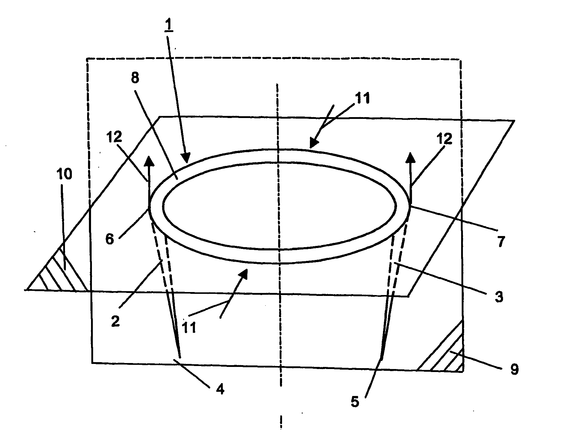
[0014] As shown in FIG. 1, the bone clamp 1 may include two branches 2, 3. The branches 2, 3 may have a first, free end 4, 5 and a second, rear end 6, 7, respectively, and may define a plane 9. The rear ends 6, 7 may be connected to one another by a bridge 8, which may be elastically deformable. The branches 2, 3 and bridge 8 may be made of a single piece of material or may be separate components which may be joined together. It should, however, be understood that those of ordinary skill in the art will recognize many modifications and substitutions which may be made to various elements of the present invention.

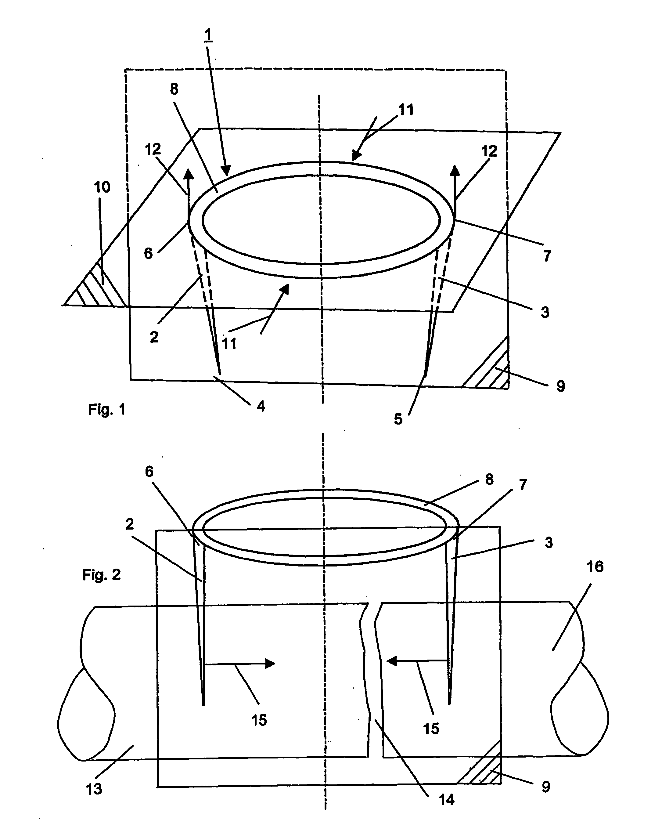
[0015] The bone clamp 1 may have a first, tension-free state (i.e., undeformed, unstressed state) such as shown in FIG. 1 and a second, tensioned state (i.e., deformed, stressed state) such as shown in FIG. 2. In the undeformed state, the free ends 4, 5 may be a first distance apart and the rear ends 6, 7 may be a second distance apart. In the first, undeformed state, the br...


PUM


Abstract

A bone clamp moving bone segments relative to each other. The clamp comprises a first and second branch and a bridge connecting the first and second branch. Each branch may have a free end and a rear end. The bone clamp may have a first, undeformed state, where the branches may be angled or substantially parallel with respect to each other. The bone clamp may have a second, deformed state, where the braches may be moved from the first state. The bone clamp may be deformed using an instrument such as pliers. When the bone clamp is in the deformed state, the branches may be inserted into bone segments. Thereafter, the instrument may be disengage from the bone clamp and the clamp may return to its undeformed state. While returning to the first, undeformed, state the bone clamp may apply compressive or distraction forces on the bone segments, thereby moving the bone segments relative to each other.

Description

CROSS-REFERENCE TO RELATED APPLICATION [0001] This application is a continuation of pending International Patent Application PCT / CH2003 / 000369, filed Jun. 11, 2003, which is incorporated by reference herein in its entirety. FIELD OF THE INVENTION [0002] The present invention relates to an apparatus and method for treating bone fractures and, more particularly, to a deformable bone clamp for moving bone segments relative to each other. BACKGROUND OF THE INVENTION [0003] Bone clamps are used to engage bone segments on opposite side of a fracture and hold them together. Current bone clamps made of memory metal alloy are known and generally have a transformation temperature in the body temperature range. These clamps have disadvantages. For example, current clamps must be cooled / frozen in a refrigerator or, after being implanted, heated with a special heating apparatus, such as a coagulator, which may lead to necroses. Due to the extremely high or low temperatures during or after the im...

Claims


Application Information

Patent Timeline
IPC IPC(8): A61F2/30A61B17/00A61B17/064A61B17/068
CPCA61B17/0642A61B17/068A61B2017/00867
Inventor BEUTTER, FLORIAN
Owner SYNTHES GMBH
Why Eureka
Try Eureka