Clean line heated valve

a heated valve and clean line technology, applied in the direction of lift valves, valve details, valve types, etc., can solve the problems of unfavorable maintenance, inability to steam sterilize the valve outlet, and downstream side of the valve and valve outl

Inactive Publication Date: 2006-07-06
YEWDALL GARY WAYNE +1
View PDF25 Cites 54 Cited by
  • Summary
  • Abstract
  • Description
  • Claims
  • Application Information

AI Technical Summary

Benefits of technology

[0015] The present invention addresses the shortcomings discussed with the current processes and prior inventions. It is an object of the present invention to provide a cleanable heated valve capable of achieving conditions in the downstream side of the valve and outlet that are unfavourable for microbiological activity by assisting in the drying process of the downstream side of the valve body and outlet and maintaining said valve areas dry and at an elevated temperature after use.

Problems solved by technology

Whilst there are commercially available techniques to maintain water quality within the closed piping system, maintaining unfavourable conditions for microbiological activity in the downstream side of the valve and valve outlet that is exposed to the environment, can be a problem especially in systems below 60° C.
It is also not practical to steam sterilise a valve outlet where the water is frequently required.
Steam can also be a safety hazard and for the abovementioned reasons steam is not a good general solution to the problem.
Like steam, these methods introduce complications and can only be effective during the sterilisation / sanitisation cycle once removed or when the outlet is reused contamination can begin to reoccur.
Another example could be the transfer of a product that is a liquid above a specific temperature but solidifies below that specific temperature or liquids that tend to create cleaning difficulties at certain temperatures and require cleanable systems including valves.
Said valves can often provide “cold spots” in such applications due to the mass of metal exposed to the colder outer environment making it difficult to achieve the required treatment temperatures.
Whilst these techniques are successful on interconnecting pipes it is difficult to provide enough energy from the outer exposed surfaces to heat-up the thick mass of metal found in smooth cleanable type valves to achieve the required temperatures on the inside surfaces of the valve.
Heat tracing and associated protection coverings when applied to valve bodies can be bulky, difficult to apply efficiently and difficult reapply after removal for maintenance and can create external cleaning issues in hygienic industries.
The resulting nooks and crannies provide areas for product to lodge, harbouring microbiological contamination and creating difficulties for cleaning.
This makes the said valves unsuitable for hygienic industries or where cleaning or sterilisation is an issue.
Also, given that the heating element is in contact with the process fluids, there are potential issues with localised hot spots that can denature proteins and certain food products, gaps where product and wastes can lodge between the heater and valve body.
It would also be difficult for the said valves to comply with the material compatibility, surface finish, certification and traceability requirements of the food and health science industries.

Method used


Image

  • Clean line heated valve
  • Clean line heated valve
  • Clean line heated valve

Examples


Embodiment Construction

[0030] Embodiments of the present invention are described, by way of example only, by reference to the accompanying drawings, it should be noted that the following description is not intended as limiting the broader aspects of the present invention.
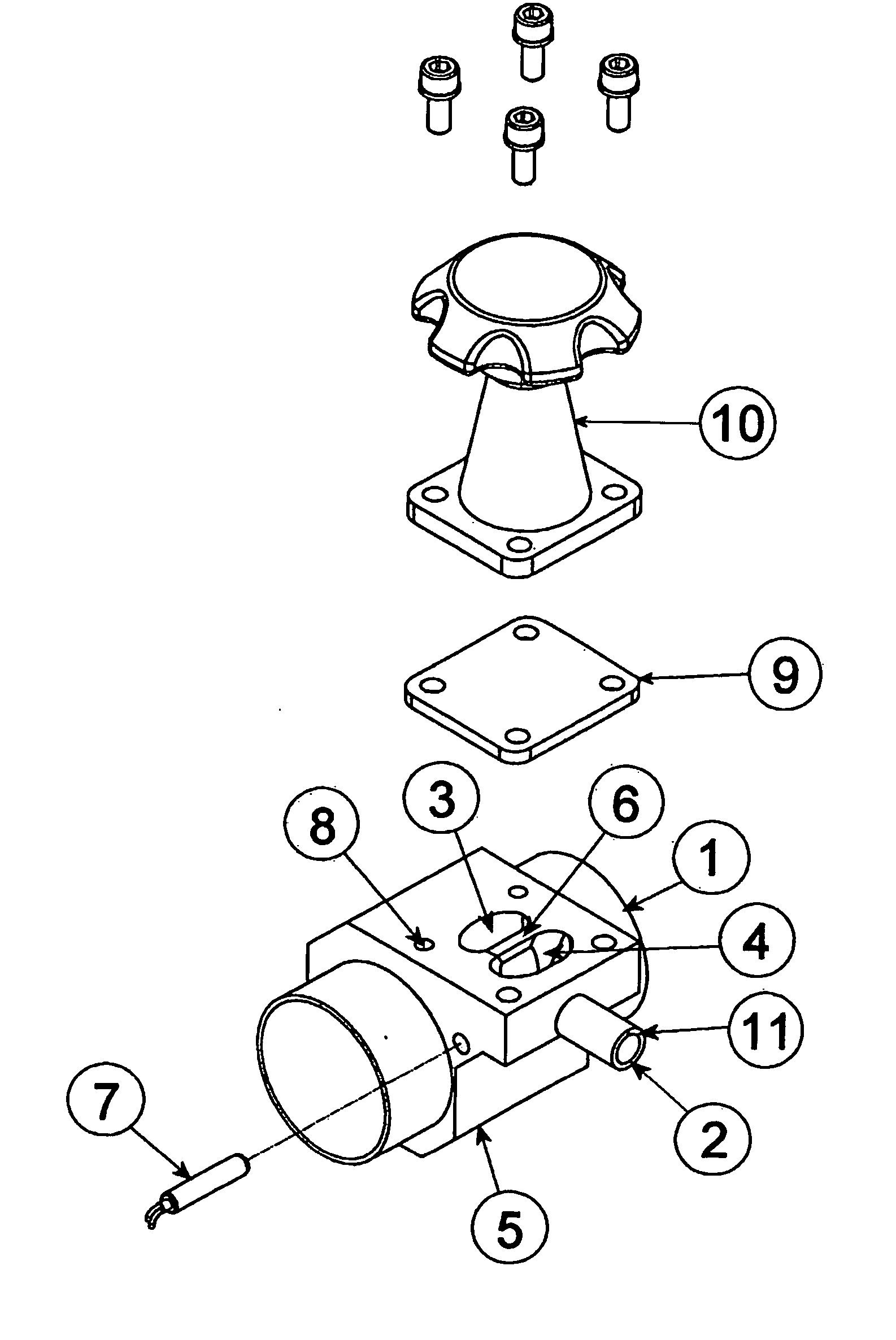
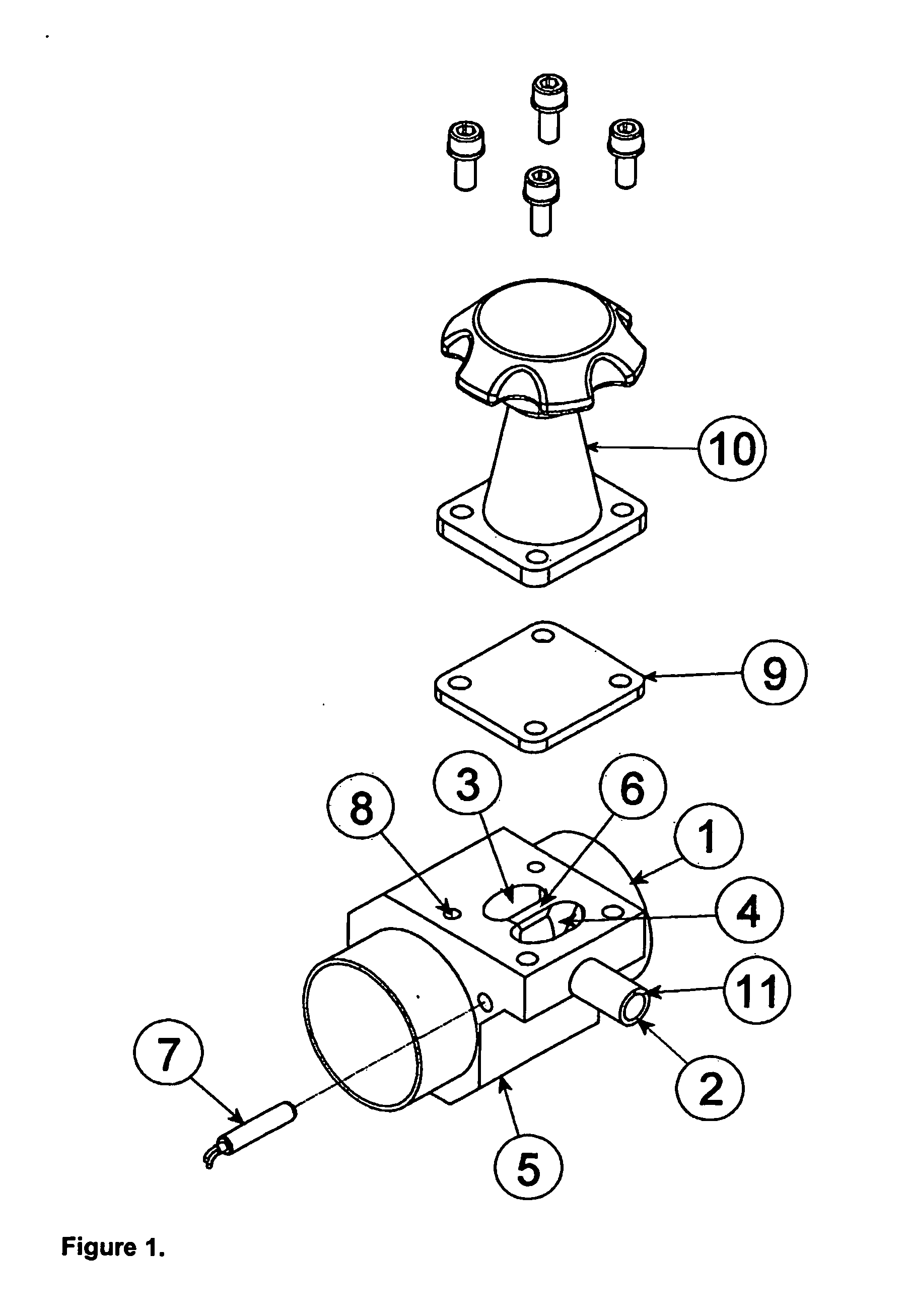
[0031]FIG. 1

[0032]FIG. 1 is a 3-Dimensional view of a cleanable heated valve body in accordance with the present invention.

[0033] The upstream connector (1), shown attached to the cleanable heated valve body (5), is represented as a perpendicular flow line close coupled to the upstream contoured void (3).

[0034] It should be appreciated, however, that the upstream connector is an attachment to supply the medium to the cleanable heated valve body and therefore can take a number of other forms other than that displayed, including but not limited to; another connected valve, plain inlet tube or pipe, associated tube or pipe fittings, vessel or tank wall, wall of sterilising apparatus or the like.

[0035] The downstream connector (2) shown a...


PUM


Abstract

A valve of cleanable design capable of maintaining unfavourable conditions for microbial activity on the downstream side and/or outlet of the valve, said valve comprising: A smooth and contoured body (5) with an integral upstream connector (1), downstream connector and defined fluid flow path; a flexible sealing membrane (9) being: (i) selectively moveable into contact with the valve body to close the valve; (ii) selectively moveable out of contact with the valve body to open the valve; (iii) selectively operable to a range of positions to vary the flow rate of fluid through said valve; a defined internal shape that allows the fluid to drain out of the valve body; an elongated heater (7) secured into the valve body in a location so as not to be contact with the fluid or disrupt the internal smooth and contoured body, the heater being operative to heat the valve body to a predetermined temperature.

Description

FIELD OF THE INVENTION [0001] The invention relates to a smooth and contoured heated valve capable of: [0002] Providing a dry and biostatic environment on the downstream side and / or outlet of the valve. [0003] Throttling and isolating fluids best handled in a cleanable valve, possessing enhanced properties at elevated temperatures; [0004] Assist in maintaining sterilising conditions on the process contact side of a valve attached to sterilising apparatus BACKGROUND OF THE INVENTION [0005] A typical application for the cleanable heated valve is in process industries that require a supply of high purity water within prescribed contamination limits supplied in custom designed systems with specific materials, finishes, process conditions and cleaning requirements, where cleaning can range from simple common cleaning methods to sanitisation and or sterilisation. [0006] Quite often high purity water is required for specific operations in a number of industries, and is required to be suppl...

Claims


Application Information

Patent Timeline
Patent Type & Authority Applications(United States)
IPC IPC(8): F16K49/00F16K7/12F16K7/16
CPCF16K7/126F16K7/16F16K49/002Y10T137/6606
Inventor YEWDALL, GARY WAYNEPICKERING, GRAHAM WILLIAM
Owner YEWDALL GARY WAYNE
Why Eureka
Try Eureka