Rotating control head radial seal protection and leak detection systems

a technology of radial sealing protection and leak detection, which is applied in the direction of survey, insulation, and borehole/well accessories, etc., can solve the problems of hazard to the drilling crew and equipment, significant expenditure of manpower and equipment, and maintenance of rotating equipmen

Inactive Publication Date: 2006-07-06
WEATHERFORD TECH HLDG LLC
View PDF99 Cites 139 Cited by
  • Summary
  • Abstract
  • Description
  • Claims
  • Application Information

AI Technical Summary

Problems solved by technology

Drilling a wellbore for hydrocarbons requires significant expenditures of manpower and equipment.
Rotating equipment requires maintenance as the drilling environment produces forces, elevated temperatures and abrasive cuttings detrimental to the longevity of seals, bearings, and packing elements.
In many instances, the formations produce fluid pressure that may be a hazard to the drilling crew and equipment unless properly controlled.
The axial movement of the drill pipe along with other forces experienced in the drilling operation, some of which are discussed below, causes wear and tear on the bearing and seal assembly and the assembly subsequently requires repair.
The thrust generated by the wellbore fluid pressure, the radial forces on the bearing assembly and other forces cause a substantial amount of heat to build in the conventional rotating control head.
The heat causes the seals and bearings to wear and subsequently require repair.
If the radial seals are not sufficiently cooled, the localized temperature at the sealing surface will rise until the temperature limitations of the seal material is reached and degradation of the radial seal begins.
The faster the rise in temperature means less life for the radial seals.
When this value is exceeded, the radial seal fails prematurely.
Thus, the PV factor is the limitation to the amount of pressure and RPM that a rotating control head can be expected to perform.
When the PV factor is exceeded, either excessive heat is generated by friction of the radial seals on the rotating inner member, which causes the seal material to break down, or the pressure forces the radial seal into the annular area between the rotating inner member and stationary outer member which damages the deformed seal.

Method used


Image

  • Rotating control head radial seal protection and leak detection systems
  • Rotating control head radial seal protection and leak detection systems
  • Rotating control head radial seal protection and leak detection systems

Examples


Embodiment Construction

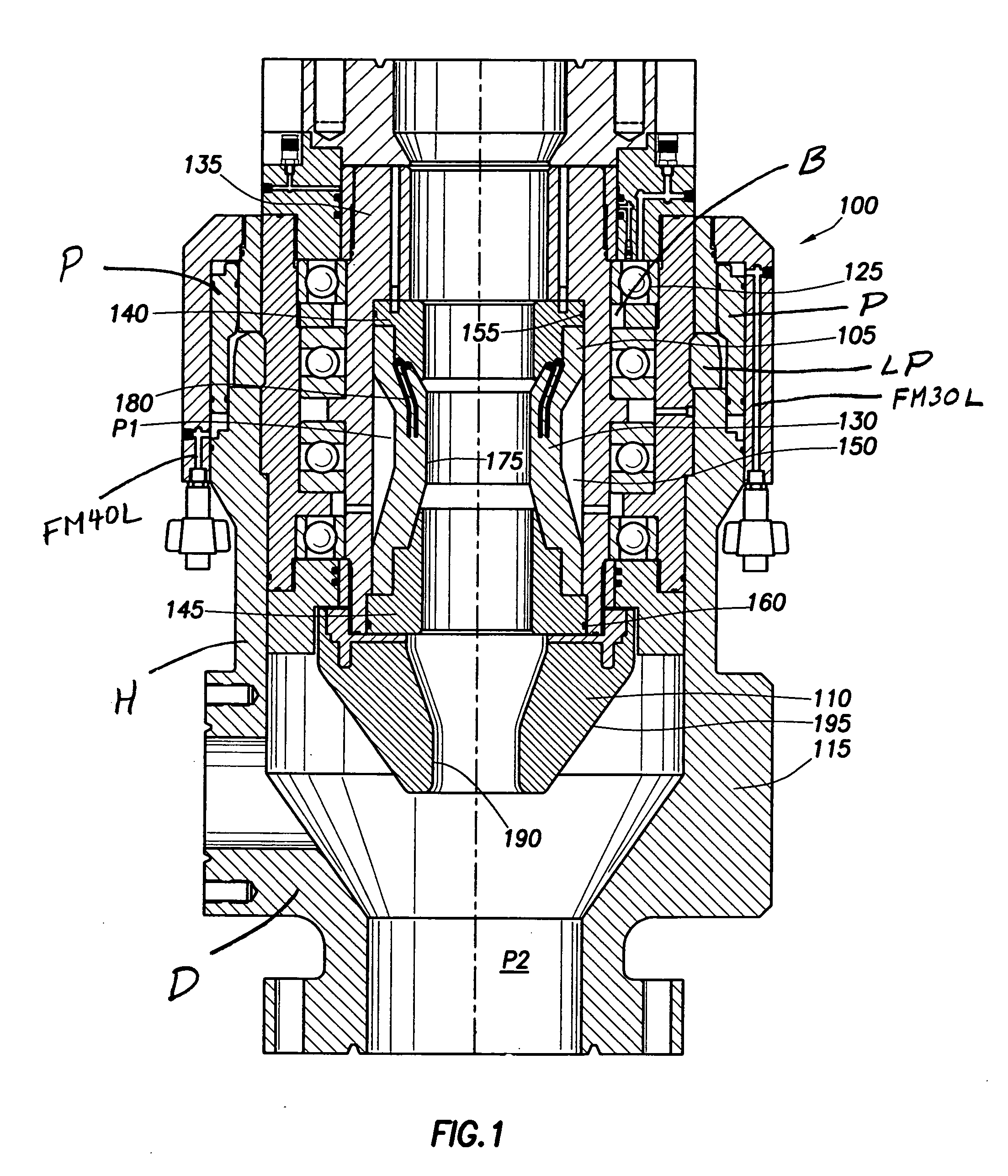
[0060] Generally, the present invention relates to a rotating control head for use with a drilling rig. Typically, an inner portion or member of the rotating control head is designed to seal around a rotating tubular and rotate with the tubular by use of an internal sealing element and bearings. Additionally, the inner portion of the rotating control head permits the tubular to move axially and slidably through the rotating control head on the drilling rig.

[0061]FIG. 1 is a cross-sectional view illustrating the rotating control head, generally indicated at 100, in accord with the present invention. The rotating control head 100 preferably includes an active seal assembly 105 and a passive seal assembly 110. Each seal assembly 105, 110 includes components that rotate with respect to a housing 115. The components that rotate in the rotating control head are mounted for rotation about a plurality of bearings 125.

[0062] As depicted, the active seal assembly 105 includes a bladder supp...


PUM


Abstract

A system and method for reducing repairs to radial seals used in a rotating control head used while drilling is disclosed. Also, a system and method to detect leaks in the rotating control head and a latching system to latch the rotating control head to a housing is disclosed.

Description

CROSS-REFERENCE TO RELATED APPLICATIONS [0001] This application is a continuation-in-part of U.S. application Ser. No. 10 / 285,336 entitled “Active / Passive Seal Rotating Control Head” filed Oct. 31, 2002, and U.S. application Ser. No. 10 / 995,980 entitled “Riser Rotating Control Device” filed Nov. 23, 2004, both of which are incorporated by reference in their entirety for all purposes.STATEMENTS REGARDING FEDERALLY SPONSORED RESEARCH OR DEVELOPMENT [0002] Not applicable. REFERENCE TO A MICROFICHE APPENDIX [0003] Not applicable. BACKGROUND OF THE INVENTION [0004] 1. Field of the Invention [0005] Embodiments of the present invention relate generally to a method and a system for a rotating control head used in a drilling operation. More particularly, the invention relates to a remote leak detection system, radial seal protection system and an improved cooling system for a rotating control head and a method for using the systems. The present invention also includes a leak detection system...

Claims


Application Information

Patent Timeline
Patent Type & Authority Applications(United States)
IPC IPC(8): E21B17/10
CPCE21B33/085F16J15/324F16K41/046E21B47/10E21B36/001
Inventor BAILEY, THOMAS F.CHAMBERS, JAMES W.HANNEGAN, DON M.GRAVOUIA, MARK F.
Owner WEATHERFORD TECH HLDG LLC
Why Eureka
Try Eureka