High dielectric fluid joint gasket

a dielectric fluid joint, high-dielectric technology, applied in the direction of engine seals, cable inlet sealing means, cable terminations, etc., can solve the problems of insufficient electrogalvanic corrosion prevention, and inability to achieve the desired electrogalvanic corrosion of adjacent components, and achieve high dialectic insulating properties, promote optional adhesion of elastomer materials, and promote sealing.

Inactive Publication Date: 2006-07-06
FEDERAL MOGUL WORLD WIDE
View PDF31 Cites 18 Cited by
  • Summary
  • Abstract
  • Description
  • Claims
  • Application Information

AI Technical Summary

Benefits of technology

[0006] A gasket constructed according to the present invention has an exposed gasket surface of PEEK material in the regions prone to abrasion, such as around the bolt holes, and preferably covering the entire gasket core. According to a first embodiment, the gasket core is fabricated of steel or other metal material and then coated with the PEEK material. The PEEK material has the advantage of offering high dialectic insulating properties which serves as an electrical barrier to disrupt the metallic conductive pathway through the gasket that had heretofore been identified as at least contributing to the establishment of an electrogalvanic cell which caused corrosion of the adjoining components that are clamped. In a sec...

Problems solved by technology

In some instances, it has been found that the adjacent components are susceptible to corrosion and it is believed that the metal gasket is serving at least in part as a conductive pathway between the components to establish an undesirable corrosion cell that, in the presence of the fluid, leads to undesirable electrogalvanic corrosion of the adjacent components.
While such a coating provides some level of insulating value in some areas, it has been found that around the bolt holes and near mold standoff locations on the gasket, at points where the ma...

Method used


Image

  • High dielectric fluid joint gasket
  • High dielectric fluid joint gasket
  • High dielectric fluid joint gasket

Examples


Embodiment Construction

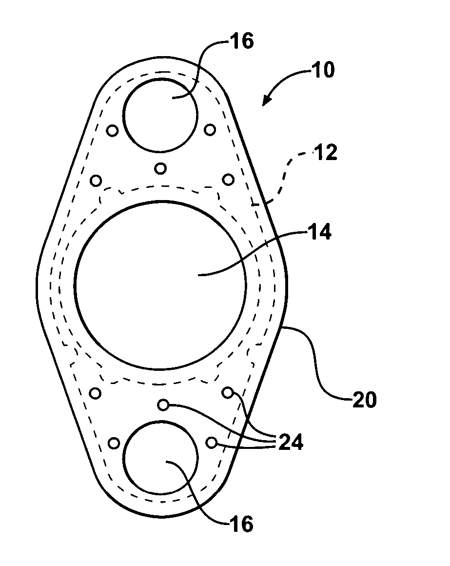
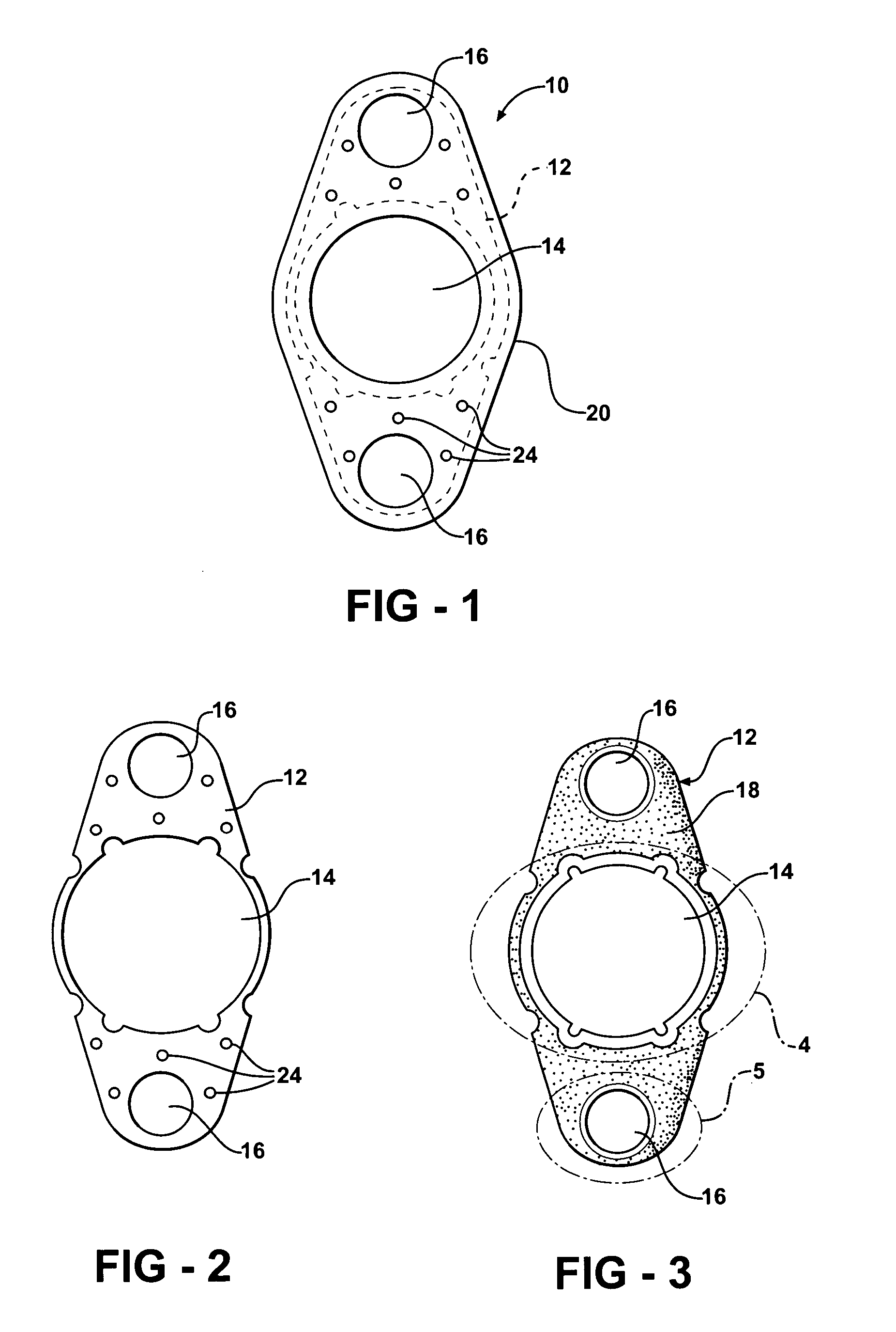
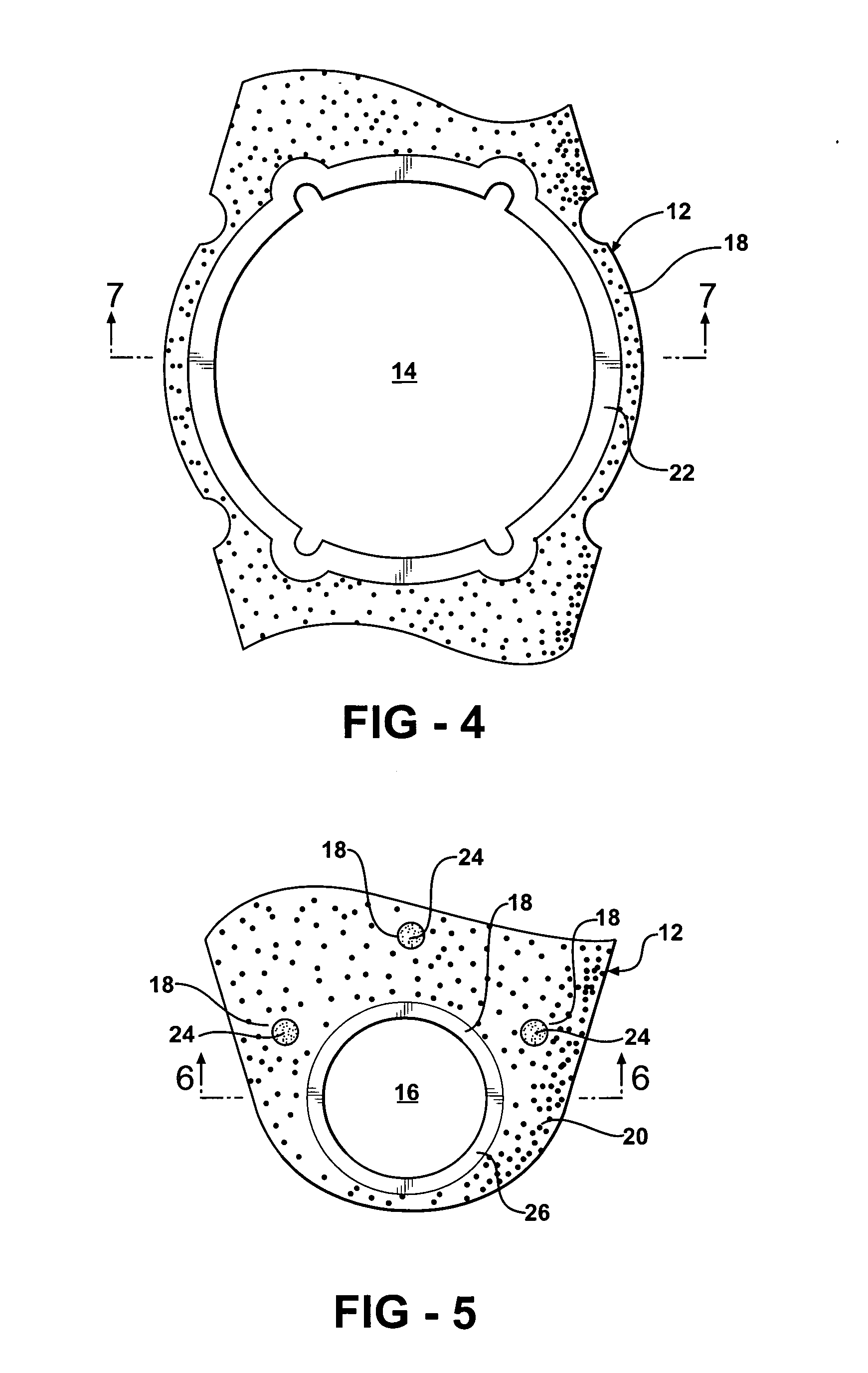
[0019] A metal gasket constructed according to a presently preferred embodiment of the invention is shown generally at 10 in FIGS. 3 and 4 and comprises a gasket core 12 (FIG. 1) which serves as the structural framework or backbone of the gasket. The core 12 is formed with at least one fluid opening 14 for conveying a fluid through the gasket 10. The gasket 10 may comprise, for example, an oil cooler gasket designed to be clamped between an oil cooler and an engine block (neither of which are shown) for forming a fluid-tight seal therebetween. The gasket 10 further includes at least one and preferably at least two bolt hole openings 16 formed through the core 10 in spaced relation to the fluid opening 14 and designed to accommodate the passage of mounting bolts (not shown) used for fastening the oil cooler to the block and, when tightened, to compress the gasket 10 to establish the fluid-tight seal between the oil cooler and block to prevent the leakage of fluid conveyed between the...


PUM


Abstract

A gasket assembly has at least one fluid-conveying opening and at least one bolt hole. The gasket includes PEEK material that may be applied as a layer to at least a portion of a metal core of the gasket. A layer of elastomeric sealing material is applied to at least a portion of the PEEK material.

Description

[0001] This invention claims priority to U.S. Provisional Patent Application No. 60 / 614,250, filed Sep. 29, 2004.BACKGROUND OF THE INVENTION [0002] 1. Technical Field [0003] This invention relates generally to metal gaskets, and more particularly to those used in applications in which the gasket is clamped between adjacent components in the presence of an electrolytic fluid which, if not properly protected, could result in the gasket serving as a metallic conductive pathway leading to electrolytic corrosion of the adjacent component parts. [0004] 2. Related Art [0005] Metal gaskets are used in numerous applications to provide a fluid-tight seal between adjacent components. One such application is a gasket for an oil cooler core. The gasket is of the type having a metal embossment surrounding the fluid opening to be sealed and including a plurality of bolt hole openings to accommodate the passage of bolts used to clamp the components to one another with the gasket therebetween. In so...

Claims


Application Information

Patent Timeline
IPC IPC(8): F16J15/08
CPCF16J15/0818F16J15/122F16J2015/0856F16J15/08
Inventor CASLER, ARVIDCOFRIN, JOHN B.BOMMAREDDY, VIJAY
Owner FEDERAL MOGUL WORLD WIDE
Why Eureka
Try Eureka