Lithographic apparatus, excimer laser and device manufacturing method

a technology of excimer laser and lithographic apparatus, which is applied in the direction of optical instruments, photomechanical apparatus, instruments, etc., can solve the problems of limiting process latitude, cd-focus error is a particular problem, and conventional lithographic apparatus do not directly address the problem of cd-focus error, etc., to achieve the effect of enhancing the depth of focus

Active Publication Date: 2006-07-06
ASML NETHERLANDS BV
View PDF13 Cites 31 Cited by
  • Summary
  • Abstract
  • Description
  • Claims
  • Application Information

AI Technical Summary

Benefits of technology

[0017] The present inventors have identified the following. Techniques are known to enhance the depth of focus for a projection lithographic process by manipulating the spectral distribution of radiant intensity of the projection beam. Generally, radiation used for exposure is provided by an excimer laser; for example, a KrF excimer laser operating at 248 nm wavelength or an ArF excimer laser operating at 193 nm wavelength may be used. The spectral distribution of radiant intensity provided by such lasers comprises a spectral intensity peak having a symmetric shape with respect to a peak wavelength λp. The bandwidth of the spectral peak may be expressed as a full-width half-maximum bandwidth (referred to as FWHM bandwidth) or alternatively as the bandwidth within which 95% of the total output power of the laser is contained (referred to as the E95 bandwidth), with the peak wavelength λp typically centered within said bandwidths.
[0021] This addition of (generally defocused) images has an effect on the image contrast at wafer level. A relatively large laser bandwidth introduces a relatively low image contrast at wafer level, but at the same time the available depth of focus is increased. However, above mentioned problem of contact holes closing earlier in one defocus direction, as compared to the other defocus direction, limiting the lithographic process latitude, remains.
[0022] It is an object of the present invention to obviate or mitigate one or more of the aforementioned problems in the prior art. In particular, it is an object of the invention to provide improved control over CD-focus dependency.
[0023] The present inventors have identified that providing an asymmetric spectral intensity distribution of the laser radiation can be used to compensate an asymmetry of imaging parameters (such as printed CD) with respect to focus and / or best focus, and in particular to reduce the asymmetry of an asymmetric CD-focus dependency.
[0025] The present invention provides an advantage of adjustment of the spectral distribution of radiant intensity I(λ): using data relating to exposure at a first focal position and exposure at a second focal position, it is possible to either match system to system focus behavior or to enhance the symmetry of focus behaviour with respect to a position of best focus.

Problems solved by technology

With conventional projection lithographic techniques it is well known that an occurrence of a variance in CD for both semi-dense and isolated features may limit the process latitude (i.e., the available depth of focus in combination with the allowed amount of residual error in the dose of exposure of irradiated target portions for a given tolerance on CD).
This problem arises because features on the mask having the same nominal critical dimensions will print differently depending on the amount of defocus (out of a plane of best focus) of the part of the target portion where the feature is imaged, due to, for example, substrate topography, image curvature or substrate unflatness.
The phenomenon CD-focus error is a particular problem in photolithographic techniques.
Conventional lithographic apparatus do not directly address the problem of CD-focus error.
However, such a measure to reduce CD-focus error may lead to an increase of other lithographic prosess errors or sensitivities, and may therefore still adversely affect the process latitude.
In a situation where different lithographic projection apparatus (of the same type and / or of different types) are to be used for the same lithographic manufacturing process step, there is a problem of mutually matching the corresponding different CD-focus dependencies, such as to reduce CD variations occurring in the manufacturing process.
Therefore there is the problem of controlling and keeping within tolerance a desired CD-focus dependency.
With conventional projection lithographic techniques it is well known that an occurrence of a variance in CD due to focus variations and exposure dose variations may limit the process latitude.

Method used


Image

  • Lithographic apparatus, excimer laser and device manufacturing method
  • Lithographic apparatus, excimer laser and device manufacturing method
  • Lithographic apparatus, excimer laser and device manufacturing method

Examples


Embodiment Construction

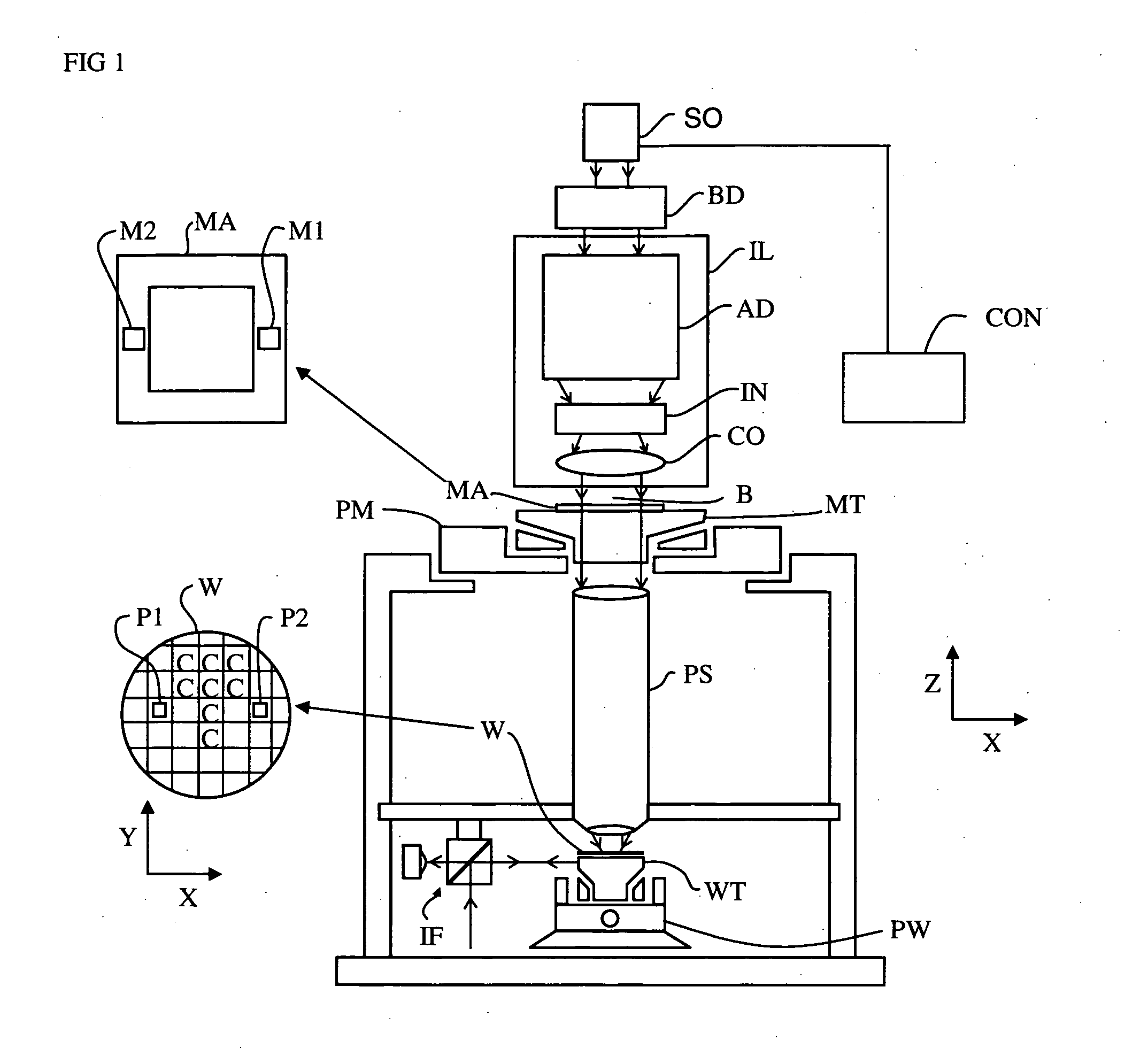
[0057]FIG. 1 schematically depicts a lithographic apparatus according to a particular embodiment of the invention. The apparatus comprises: [0058] an illumination system (illuminator) IL for providing a projection beam PB of radiation (e.g., UV radiation or EUV radiation). [0059] a first support structure (e.g., a mask table) MT for supporting a patterning device (e.g., a mask) MA and connected to first positioning actuator PM for accurately positioning the patterning device with respect to item PL; [0060] a substrate table (e.g., a wafer table) WT for holding a substrate (e.g., a resist-coated wafer) W and connected to second positioning actuator PW for accurately positioning the substrate with respect to item PL; and [0061] a projection system (e.g., a refractive projection lens) PL for imaging a pattern imparted to the projection beam PB by patterning device MA onto a target portion C (e.g., comprising one or more dies) of the substrate W.

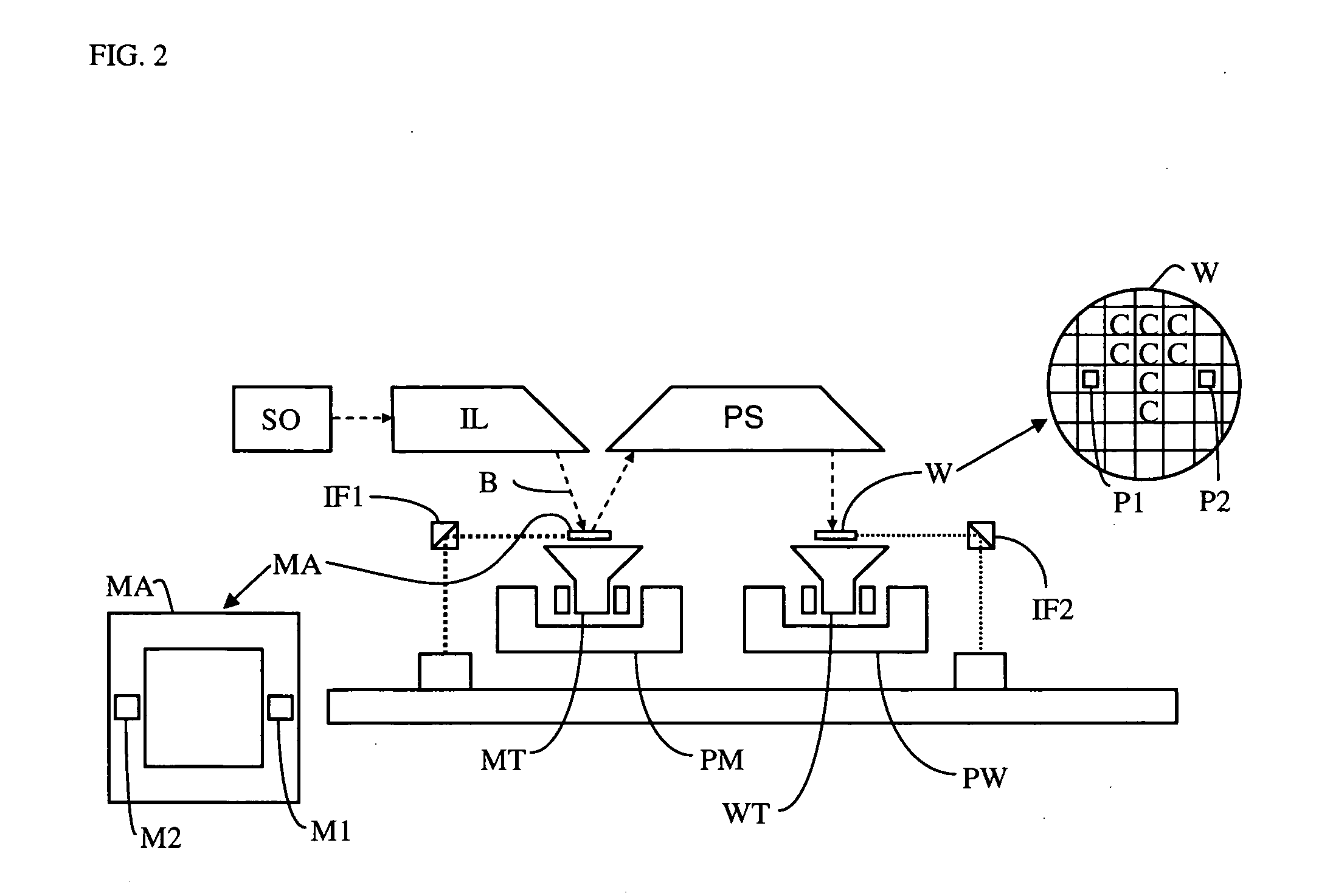
[0062] As here depicted, the apparatus i...


PUM


Abstract

A CD-pitch dependency for a lithographic pattern printing process is related to the spectral intensity distribution of radiation used for projecting the pattern. A CD-pitch dependency can vary from one system to another. This can result in an iso-dense bias mismatch between systems. The invention addresses this problem by providing a lithographic apparatus including an illumination system for providing a projection beam of radiation, a projection system for projecting a patterned beam onto a target portion of a substrate, and a substrate table for holding the substrate, with a controller to provide an adjustment of the spectral distribution of radiant intensity of the projection beam. The adjustment of the spectral intensity distribution is based on data relating to an iso dense bias, and comprises a broadening of the spectral bandwidth or a change of shape of the spectral intensity distribution.

Description

RELATED APPLICATIONS [0001] This is a continuation in part of U.S. patent application Ser. No. 11 / 019,531, filed Dec. 23, 2004, hereby incorporated by reference.BACKGROUND OF THE INVENTION [0002] 1. Field of the Invention [0003] The present invention relates to a lithographic apparatus, an excimer laser and a device manufacturing method. This invention also relates to a device manufactured thereby. [0004] 2. Description of the Related Art [0005] A lithographic apparatus is a machine that applies a desired pattern onto a target portion of a substrate. Lithographic apparatus can be used, for example, in the manufacture of integrated circuits (ICs). In that circumstance, a patterning device, which is alternatively referred to as a mask or a reticle, may be used to generate a circuit pattern corresponding to an individual layer of the IC, and this pattern can be imaged onto a target portion (e.g., comprising one or several dies) on a substrate (e.g., a silicon wafer) that has a layer of...

Claims


Application Information

Patent Timeline
Patent Type & Authority Applications(United States)
IPC IPC(8): G03B27/72
CPCG03F7/70558G03F7/70575G03F7/70641
Inventor DE KRUIF, ROBERTUS CORNELIS MARTINUSBRULS, RICHARD JOSEPHCASTENMILLER, THOMAS JOSEPHUS MARIADE KLERK, JOHANNES WILHELMUSBUURMAN, ERIK PETRUS
Owner ASML NETHERLANDS BV
Why Eureka
Try Eureka