Achromatic imaging lens with extended depth of focus

a technology of achromatic imaging and depth of focus, applied in the field of optics, can solve the problems of large aperture, large lateral resolution, large numerical aperture, etc., and achieve the effects of reducing chromatic aberration of incident light, extending depth of focus, and high lateral resolution of incident ligh

Inactive Publication Date: 2006-04-20
NEW SPAN OPTO TECH
View PDF4 Cites 47 Cited by
  • Summary
  • Abstract
  • Description
  • Claims
  • Application Information

AI Technical Summary

Benefits of technology

[0011] Briefly, according to an embodiment of the invention, a lens includes a diffractive surface having an etched structure and a refractive surface having a curved structure. The lens reduces chromatic aberration of incident light and extends depth of focus. In one embodiment of the present invention, the etched structure is a calculated phase pattern or a pattern that is embossed or diamond tuned. In another embodiment, the curved structure is convex shaped or concave shaped. In yet another embodiment, the lens is an imaging lens wherein high lateral resolution of incident light is preserved.

Problems solved by technology

As a result, large depth of focus requires small numerical apertures, whereas high resolution demands large apertures.
Thus, conventional optical elements cannot produce a beam with long focal depth and high lateral (or transverse) resolution concurrently.
They can only achieve increased depth of focus through aperture reduction (decreasing NA), which correspondently reduces the amount of light capturing and transversal resolution the system can attain.
However, axicons are difficult to fabricate and concentrate only a small fraction of energy into the focused beam, resulting in low light efficiency.
Yet these elements suffer from a decrease of optical power at the image plane, and from a decrease of transversal resolution that is due to obstructed aperture.
However, because of the high wavelength sensitivity of DOEs, for broadband illumination these elements suffer from unacceptably high chromatic aberration.
Wave-front coding digital restoration techniques have also been applied with ample success to resolve the focal depth / resolution imaging problem, but these approaches require additional signal and image processing, which require a large computing effort.

Method used


Image

  • Achromatic imaging lens with extended depth of focus
  • Achromatic imaging lens with extended depth of focus
  • Achromatic imaging lens with extended depth of focus

Examples


Embodiment Construction

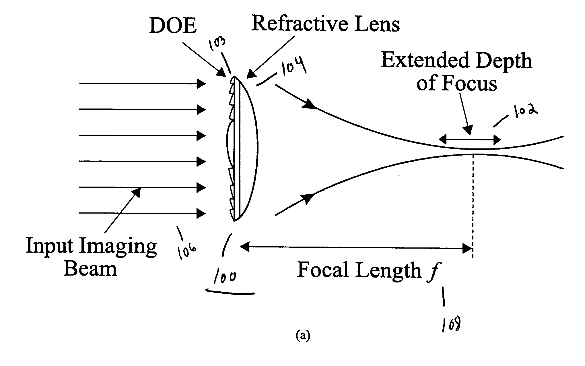
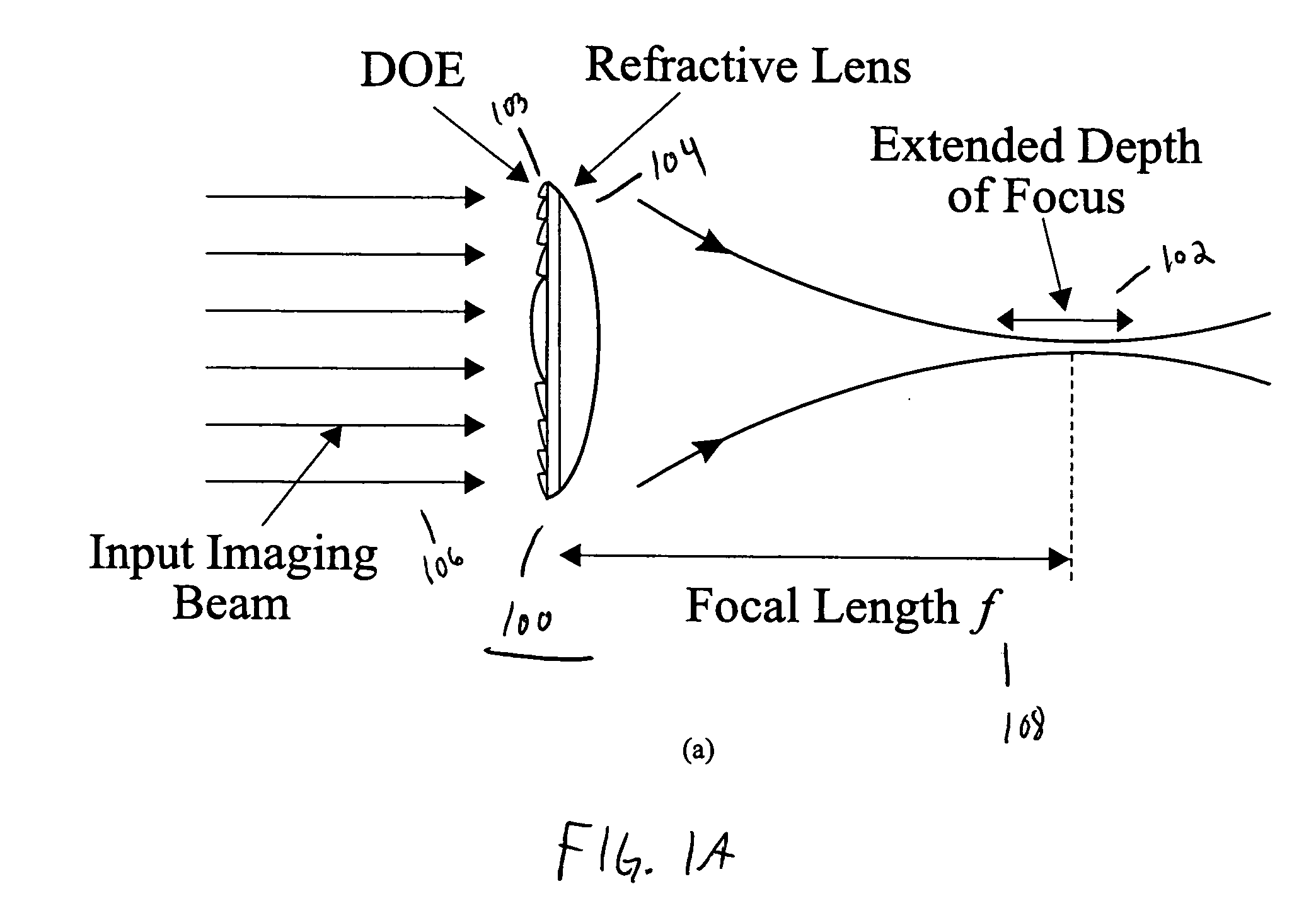
[0039] The present invention discloses a design for an achromatic hybrid refractive-diffractive lens that extends the depth of focus (DOF) without sacrificing the system's transverse resolution. The extended DOF lens combines a specially designed DOE that generates a long range of pseudo-non-diffractive rays with a corresponding refractive lens to diminish chromatic aberrations in the desired spectral band. Utilizing a hybrid refractive-diffractive device configuration simultaneously preserves the favorable properties of both the diffractive element (long focal depth) and the refractive lens (low chromatic aberration, high-energy concentration).

[0040] The present invention can be used with various optical wavebands for focal depth extension. The present invention operates in the entire visible waveband and extends the DOF of a lens tenfold, as shown in experimental results, without decreasing any lateral resolution. FIG. 1A shows a schematic of the hybrid lens 100 of the present in...


PUM


Abstract

A lens includes a diffractive surface having an etched structure and a refractive surface having a curved structure. The lens reduces chromatic aberration of incident light and extends depth of focus. In one alternative, the etched structure is a calculated phase pattern or a pattern that is embossed or diamond tuned. In another alternative, the curved structure is convex shaped or concave shaped. In yet another alternative, the lens is an imaging lens wherein high lateral resolution of incident light is preserved.

Description

STATEMENT REGARDING FEDERALLY SPONSORED-RESEARCH OR DEVELOPMENT [0001] This invention was made with U.S. Government support under contract DMI-0319169 awarded by the National Science Foundation. The Government has certain rights in the invention.CROSS-REFERENCE TO RELATED APPLICATIONS [0002] Not Applicable. INCORPORATION BY REFERENCE OF MATERIAL SUBMITTED ON A COMPACT DISC [0003] Not Applicable. FIELD OF THE INVENTION [0004] The invention disclosed broadly relates to the field of optics and more particularly relates to the field of optical imaging lenses. BACKGROUND OF THE INVENTION [0005] Optical systems that simultaneously exhibit long focal depth and high lateral resolution find considerable applications in many different fields, e.g., microscopy, optical alignment, imaging, and optical interconnection. However, according to scaling and paraxial approximations, conventional optical lenses obey the following well-known relationships: ΔX=k1λ / NA, ΔZ=k2λ / NA2,  (1) where ΔX is the mi...

Claims


Application Information

Patent Timeline
Patent Type & Authority Applications(United States)
IPC IPC(8): G02B26/08G02B5/18G02B27/42G02B3/00G02B7/00G02B9/00G02B11/00G02B13/00G02B15/00G02B17/00G02B25/00
CPCG02B5/1895G02B27/4211G02B27/0075G02B27/0025
Inventor WANG, MICHAEL RENXUNYANG, JIANWEN
Owner NEW SPAN OPTO TECH
Why Eureka
Try Eureka