Transmission for bicycle

a technology for transmission and bicycles, applied in mechanical equipment, transportation and packaging, gears, etc., can solve the problems of reducing the shifting performance of the small diameter gear to the large diameter gear, unable to achieve satisfactory shifting performance, so as to improve the shifting performance of the transmission

Inactive Publication Date: 2006-07-06
SAKAE ENG
View PDF6 Cites 5 Cited by
  • Summary
  • Abstract
  • Description
  • Claims
  • Application Information

AI Technical Summary

Benefits of technology

[0005] Taking into account the abovementioned circumstances, the present invention was conceptualized, with two objectives. The first object of the invention is to enhance the shifting performance of the transmission of the bicycle in the front chain wheel having three or more gears juxtaposed in the lateral direction with two kinds of guards, i.e., a main guard and an auxiliary guard, from the small diameter gear to the middle diameter gear and similarly, from the middle diameter gear to the large diameter gear. The second object of the invention is to prevent the chain from falling off on the side of the small diameter gear when the large diameter gear is shifted to the small diameter gear while simultaneously securing shifting performance from the small diameter gear to the large diameter gear, where the transmission is used together with the front chain wheel comprising two gears.
[0006] According to the transmission of the present invention, the guards comprise two kinds, i.e., the main guard and the auxiliary guard, wherein the auxiliary guard is installed on the main guard so as to be displaced radially in the downward direction and elastically with respect to the shaft axis of the front chain wheel, such that when the small diameter gear is shifted to the middle diameter gear, the auxiliary guard can press and shift the chain in the front chain wheel having the three gears juxtaposed in the lateral direction. Further, when the middle diameter gear is shifted to the large diameter gear, the auxiliary guard presses the chain toward the side of the large diameter gear as in the case of the conventional transmission, but since the auxiliary guard is installed on the main guard so as to be elastically displaceable, in the case of a predetermined or more pressing force, it is displaced so as to escape on the side opposite the large diameter gear. As a result, the chain can be shifted to the large diameter gear smoothly without being caught between the guard and the large diameter gear.
[0007] Further, where the transmission of the present invention is used for the front wheel chain having two gears juxtaposed in the lateral direction, the shifting property similar to that of the conventional transmission for the front chain wheel having two gears juxtaposed in the lateral direction is obtained when the small diameter gear shifts to the large diameter gear, since the auxiliary guard is displaced, and while the large diameter gear shifts to the small diameter gear, the gap between the internal guard and the tooth top of the small diameter gear becomes smaller, thus preventing the chain from jumping to the small diameter gear and falling off inwardly in the lateral direction of the bicycle.

Problems solved by technology

In the process, the chain is caught between the internal guard and the large diameter gear when the middle diameter gear is shifted to the large diameter gear, resulting in lower shifting performance.
To solve this problem, various shapes of internal guard have been proposed, none of which have succeeded in attaining satisfactory shifting performance.
Further, where the front wheel chain having two gears juxtaposed in the lateral direction and the transmission of the bicycle for the front chain wheel are combined, the chain sometimes jumps over the small diameter gear and falls off inwardly in the lateral direction of the bicycle when the large diameter gear is shifted to the small diameter gear because there is a large gap between the internal guard and the tooth top of the small diameter gear.
Further, during this process, when the conventional transmission of the bicycle extending toward the side of the shaft axis of the front chain wheel is used for the front chain wheel having two gears juxtaposed in the lateral direction, the abovementioned problem similarly occurs, in that the chain is caught between the internal guard and the large diameter gear, resulting in lower shifting performance from the small diameter gear to the large diameter gear.

Method used


Image

  • Transmission for bicycle
  • Transmission for bicycle
  • Transmission for bicycle

Examples


Embodiment Construction

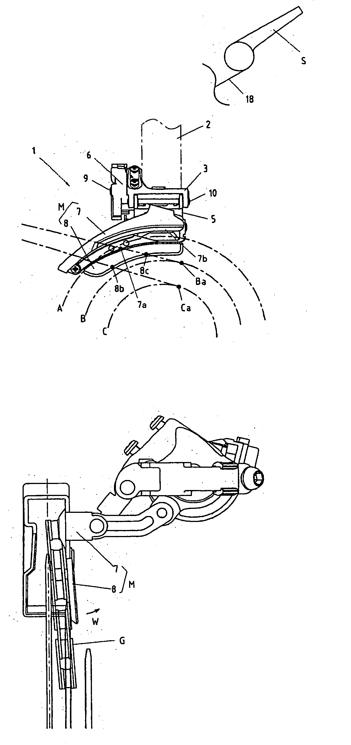
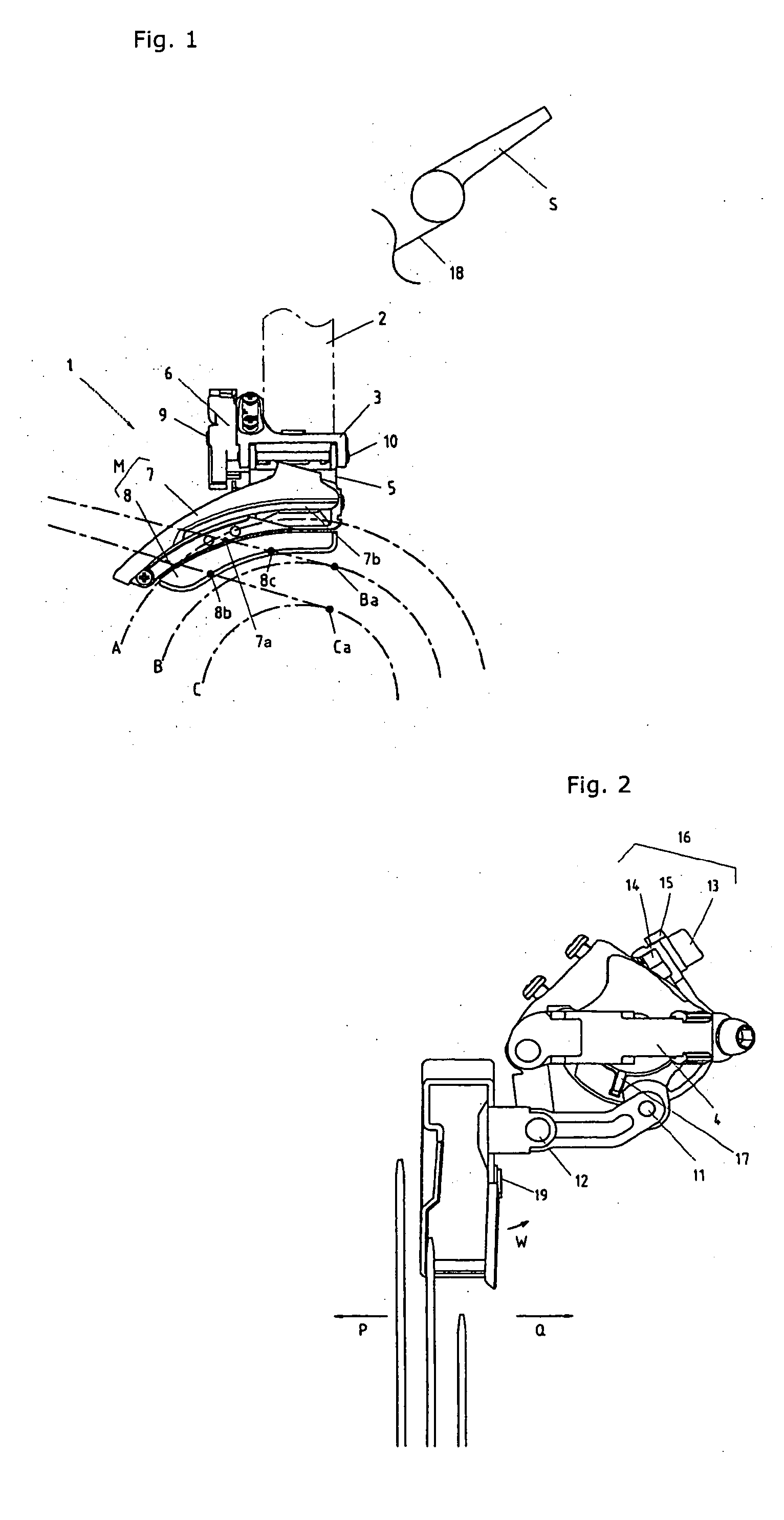
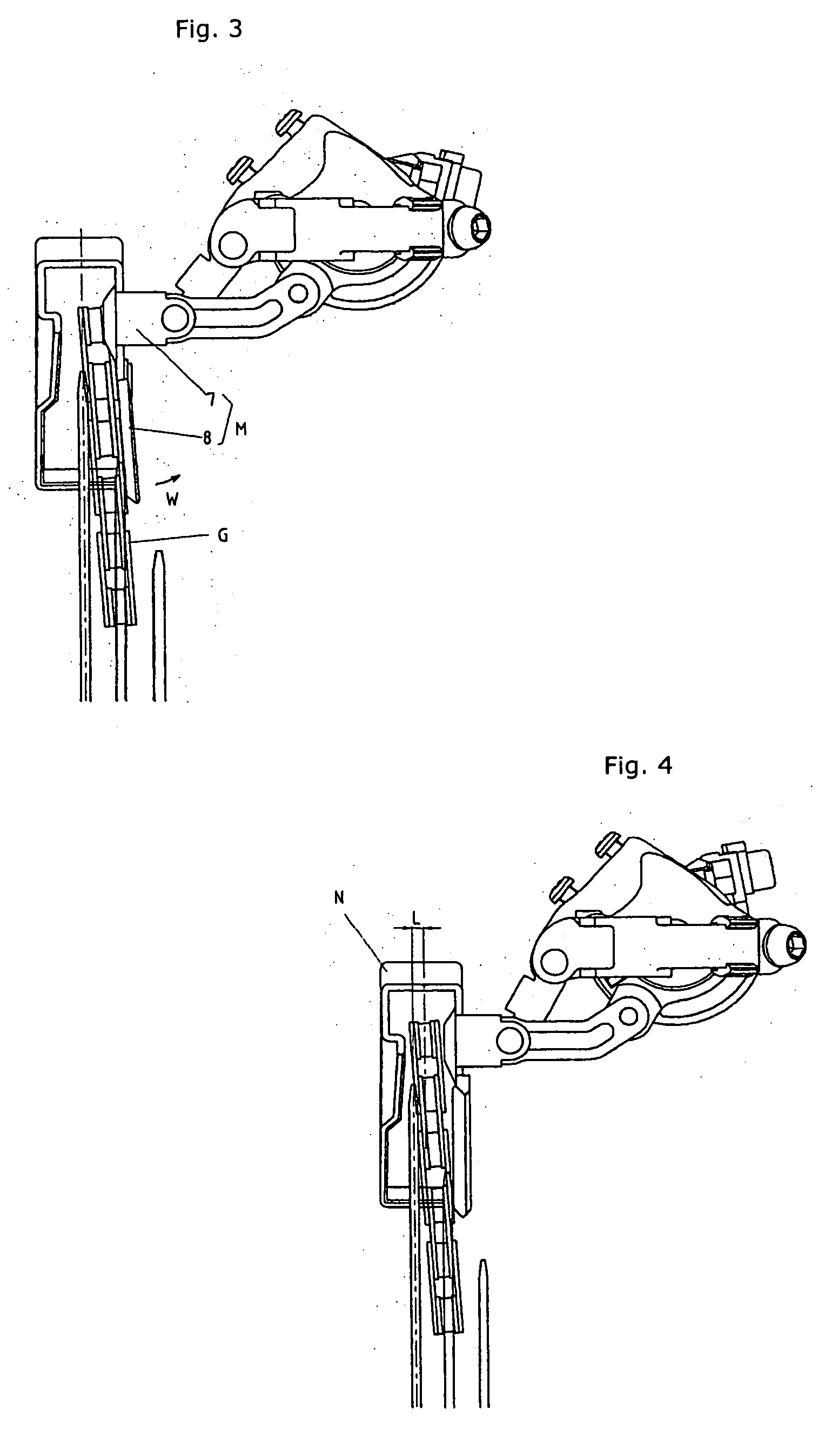
[0015] The embodiments of the present invention will be described hereinafter with reference to the drawings. As shown in FIGS. 1 and 2, the transmission for a bicycle 1 of the present invention comprises a frame 3 and a band 4 secured to a seat pipe 2, a link 6 and a link 5 pivotally mounted rotatably on the frame through a shaft 9 and a pin 10, a main guard 7 pivotally mounted on the link 5 and the link 6 rotatably through a pin 12 and a pin 11, and an auxiliary guard 8 secured to the main guard by a pin 19, wherein a guard M is formed to move in the parallel direction.

[0016] A return spring 17 is received within the interior of the link 6, and the guard M is biased by the return spring 17 inwardly in the lateral direction of the bicycle (in the direction of arrow Q). In the link 6, a wire connecting portion 16 for connecting a wire 18 extended from a shift lever S is constituted by a bolt 13, a nut 14, and a washer 15, wherein the movement of the guard M externally in the latera...


PUM


Abstract

A transmission for a bicycle for re-installing a chain in the lateral direction of the bicycle in a front chain wheel having two or more sheets of gear plates, comprising two sheets of guards, i.e., a main guard for re-installing the chain from a middle diameter gear to a large diameter gear and an auxiliary guard for re-installing the chain from a small diameter gear to the middle diameter gear, wherein the main guard is pivotally supported on a link mechanism for moving the guard in the lateral direction of the bicycle and the auxiliary guard is installed on the main guard so as to be elastically displaced.

Description

TECHNICAL FIELD [0001] The present invention relates to a transmission for a bicycle, and more specifically to a transmission for re-installing the chain in the front chain wheel of a bicycle having two or more sheets of gear plates in the lateral direction. BACKGROUND ART [0002] The widely known conventional transmission for a bicycle comprises a front chain wheel with three gears of varying diameters, small, medium and large, with each gear having different number of teeth, juxtaposed in the lateral direction, and a guard for re-installing a chain through a link mechanism. Where the chain is re-installed in the front chain wheel, for example, and a shift lever connected to the transmission of the bicycle is operated through a transmission operating wire, the transmission of the bicycle moves from the side of the small diameter gear to the side of the large diameter gear when the transmission operating wire is pulled, whereby the chain can be re-installed from the small diameter ge...

Claims


Application Information

Patent Timeline
Patent Type & Authority Applications(United States)
IPC IPC(8): F16H59/00F16H61/00B62M9/1348B62M9/1342B62M9/136
CPCB62M9/1342B62M9/136
Inventor IWASAKI, YOSHIHISA
Owner SAKAE ENG
Why Eureka
Try Eureka