Operation of electrically controlled transmissions at lower temperatures

a technology of electrically controlled transmission and low temperature, which is applied in the direction of gearing control, gearing element, belt/chain/gearing, etc., can solve the problems of shifting feel deformation, increased friction loss in electrically operable mechanically actuated valves, and increased electrical energy requirements, so as to improve fuel economy, reduce torque disturbance, and improve the performance of a transmission coupled to an internal combustion engine

Inactive Publication Date: 2008-06-05
FORD GLOBAL TECH LLC
View PDF31 Cites 5 Cited by
  • Summary
  • Abstract
  • Description
  • Claims
  • Application Information

AI Technical Summary

Benefits of technology

[0002]The performance of a transmission coupled to an internal combustion engine can be improved by using electrically actuating valves to control transmission torque converters and transmission shifting. For example, a torque converter locking clutch can be slipped at different rates to improve fuel economy and to reduce torque disturbances that a driver may feel when a transmission operates. Further, the pressure of transmission fluid that actuates transmission clutches can be controlled by an electrical actuator so that shift schedules may be varied and so that shift feel may be improved. However, at lower temperatures, frictional losses in electrically operable mechanically actuated valves can increase non-linearly, and additional electrical energy may be needed to operate a valve. As a result, shift feel may degrade and torque disturbances may be more noticeable to a driver. In addition, increased valve resistance can change valve response as well as the complexity of controlling a valve. This may be undesirable since valve performance uniformity is desired over a wide range of operating conditions.

Problems solved by technology

However, at lower temperatures, frictional losses in electrically operable mechanically actuated valves can increase non-linearly, and additional electrical energy may be needed to operate a valve.
As a result, shift feel may degrade and torque disturbances may be more noticeable to a driver.
In addition, increased valve resistance can change valve response as well as the complexity of controlling a valve.
This may be undesirable since valve performance uniformity is desired over a wide range of operating conditions.

Method used


Image

  • Operation of electrically controlled transmissions at lower temperatures
  • Operation of electrically controlled transmissions at lower temperatures
  • Operation of electrically controlled transmissions at lower temperatures

Examples


Embodiment Construction

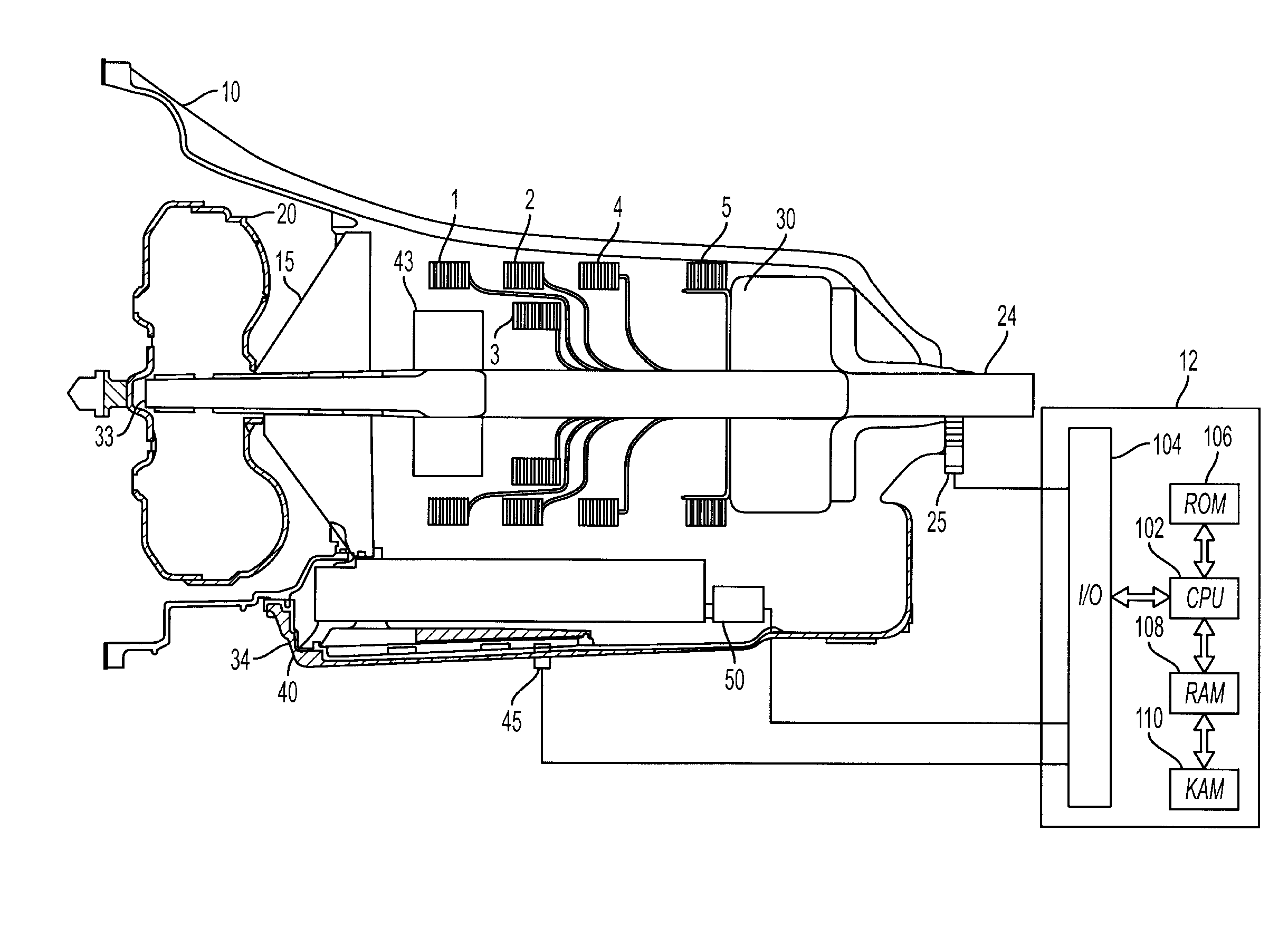
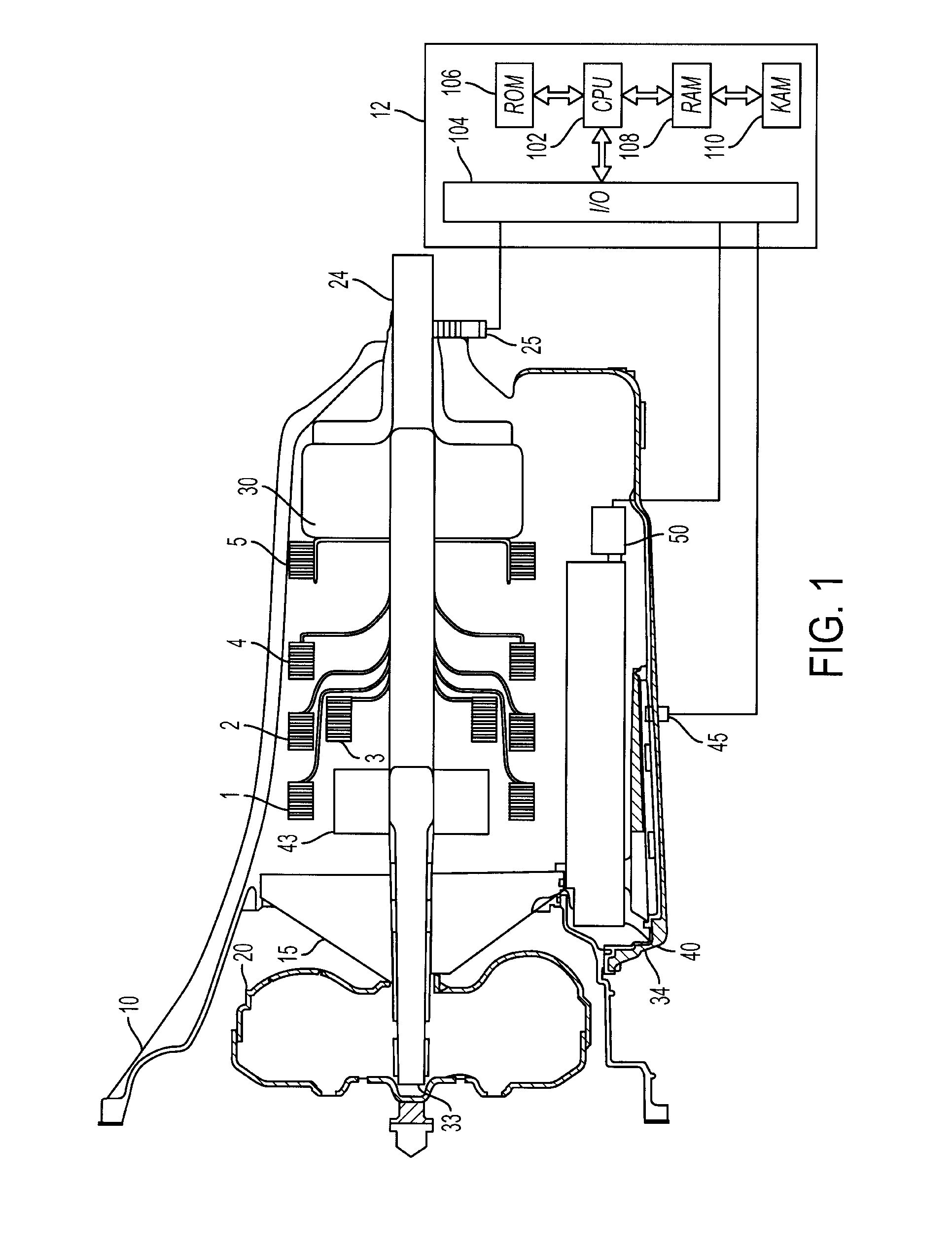
[0013]Referring to FIG. 1, a transmission 10, for managing power flow from an internal combustion engine to drive wheels of a vehicle is shown. Transmission operation is controlled by electronic controller 12. Transmission 10 includes torque converter 20 coupled to input shaft 33. Pump 15 pulls transmission fluid from pan 34 and is driven by input shaft 33 supplying pressurized fluid to torque converter 20 and to clutches 1-5 via valve body 40. Engine torque can be transferred from torque converter 20; through input shaft 33; through input gear set 43; through selected clutches 1-5; through output gear set 30; and to the output shaft 24. Spool valves (not shown) in the valve body are controlled by electrically operable mechanical valve 50, and by similar valves (not shown) to control transmission fluid pressure, control torque converter lock-up, and to apply clutches 1-5.

[0014]Controller 12 is shown in FIG. 1 as a conventional microcomputer including: microprocessor unit 102, input / ...


PUM


Abstract

A system and method for controlling electromechanical valves operating in a transmission is presented. According to the method, transmission operation can be improved by heating the valves, at least during some conditions.

Description

FIELD [0001]The present description relates to a method for controlling electrically actuated valves operating in a transmission coupled to an internal combustion engine.BACKGROUND AND SUMMARY [0002]The performance of a transmission coupled to an internal combustion engine can be improved by using electrically actuating valves to control transmission torque converters and transmission shifting. For example, a torque converter locking clutch can be slipped at different rates to improve fuel economy and to reduce torque disturbances that a driver may feel when a transmission operates. Further, the pressure of transmission fluid that actuates transmission clutches can be controlled by an electrical actuator so that shift schedules may be varied and so that shift feel may be improved. However, at lower temperatures, frictional losses in electrically operable mechanically actuated valves can increase non-linearly, and additional electrical energy may be needed to operate a valve. As a re...

Claims


Application Information

Patent Timeline
Patent Type & Authority Applications(United States)
IPC IPC(8): F16H59/00F16H61/06
CPCF16H59/72F16H61/0251Y10T477/691Y10T477/653Y10T477/65
Inventor MARANVILLE, CLAYGALE, ALLANELIE, LARRYKONEDA, PHILIP
Owner FORD GLOBAL TECH LLC
Why Eureka
Try Eureka