Modular crankset for bicycles

Active Publication Date: 2019-08-08
MIRANDA & IRMAO LDA
View PDF5 Cites 5 Cited by
  • Summary
  • Abstract
  • Description
  • Claims
  • Application Information

AI Technical Summary

Benefits of technology

[0029]FIG. 1 shows a first embodiment of

Problems solved by technology

Typically, the shaft, the spider or flange and the crank are fixed by crimping and the wheel is joined to the spider or flange with screws, thus they cannot be easily and quickly separated.
The impossibility of easily and quickly separating them leads to the need of long stops whenever it is necessary to change any of the elements.
Available in the market are some crankset systems which are presented as modular, however its assembly and disassembly process has proved

Method used


Image

  • Modular crankset for bicycles
  • Modular crankset for bicycles
  • Modular crankset for bicycles

Examples


first embodiment

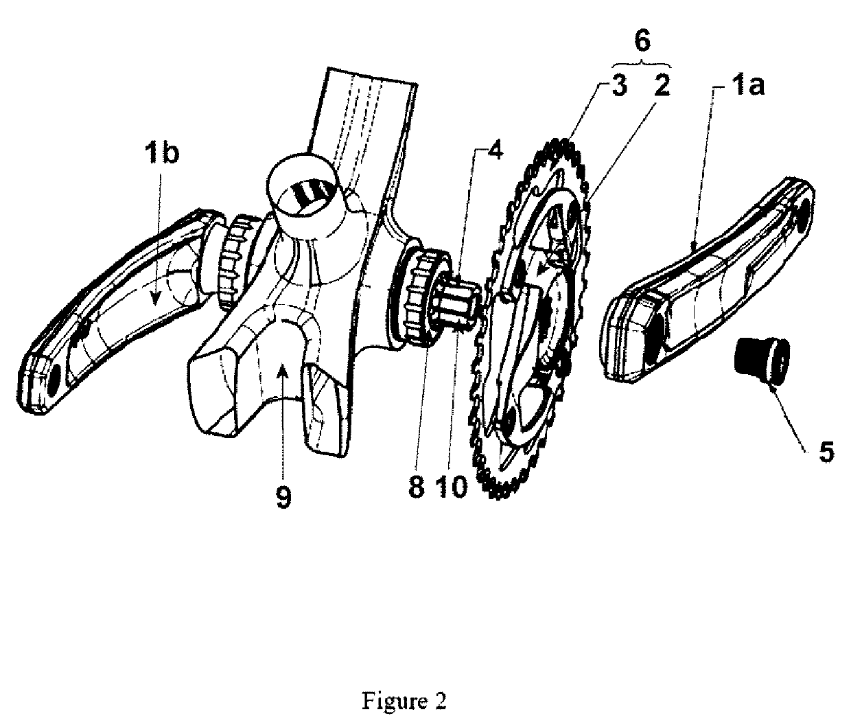
[0050]FIG. 2 shows an exploded view of the first embodiment which shows the absence of any retaining ring between the components. In fact, the modular crankset is made in a way that ensures the approximation between the different elements in a way that enables the absence of these type of elements used in the prior art.

[0051]Obviously the technology is in no way limited to the above described embodiments and someone with an average knowledge on the subject can foresee or envisage various modifications within the scope of the appended claims.

second embodiment

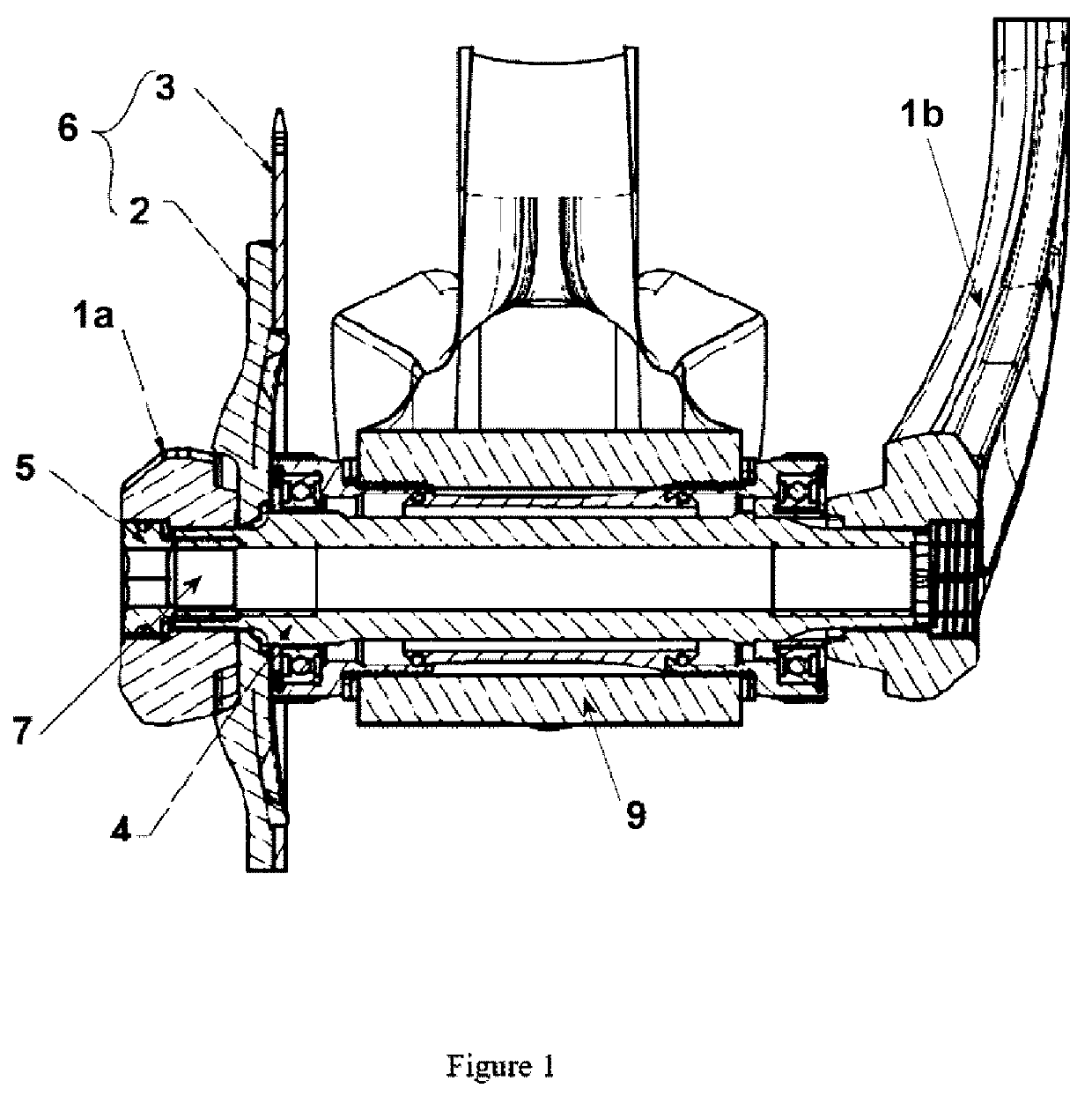
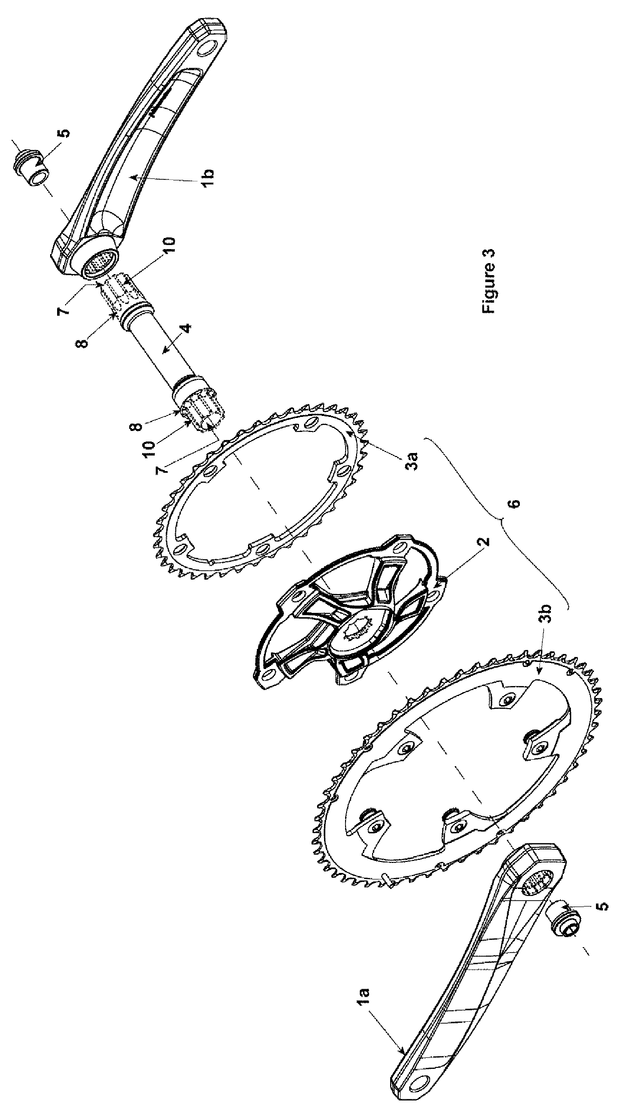
[0052]FIG. 3 shows an exploded view of a modular crankset. The modular crankset comprises a crankset shaft (4) having interfaces in the form of splines or striated areas (10) as well as retaining elements (8) in form of an overthickness on both ends. The shaft (4) also comprises two threaded ends (7) with internal threads on both ends. The striated areas (10) are of an ISIS interface.

[0053]On one end of the shaft (4), a gear wheel (6) comprising a first chain ring (3a), a spider (2) and a second chain ring (3b) is mounted. The first chain ring (3a) and the second chain ring (3b) are screwed to the spider (2). The first crank (1a) on the left is mounted to the shaft by means of screw (5). Screw (5) fixes the first crank (1a) and the gear wheel (6) to the shaft (4) by clamping said elements against the retaining element (8).

[0054]The first crank (1a) and the spider (2) both have interfaces or internal splines that match the striated area (10) (external splines) on the left end of the ...


PUM


Abstract

The present patent application describes a modular crankset for bicycles. The described modular crankset is useful for users, since it solves issues related to the speed of replacement of elements, the easiness of the replacement procedures and lowers the weight of the set without compromising the consistency and rigidity of the set. The current technology is applicable to any bicycle available in the market, including electrical bicycles, and it is especially interesting for competition bicycles, wherein the replacement of the constituent elements of the crankset should be made as quickly as possible.

Description

TECHNICAL FIELD[0001]The present patent application describes a modular crankset for bicycles.BACKGROUND OF THE INVENTION[0002]It is known in the present art the existence of a crankset system that consists of a shaft, a spider or flange, a gear wheel and a crank. Throughout this application, crankset is considered as the set of the previously referred elements.[0003]Typically, the shaft, the spider or flange and the crank are fixed by crimping and the wheel is joined to the spider or flange with screws, thus they cannot be easily and quickly separated.[0004]The impossibility of easily and quickly separating them leads to the need of long stops whenever it is necessary to change any of the elements. These changes can be necessary due to the break of any of the elements, for instance due to wear, or due to the need of adjusting any of the elements to the preferences / needs of the user, like for instance changing the chain line, the colour and length of the crank, the gear wheel size o...

Claims


Application Information

Patent Timeline
IPC IPC(8): B62M1/36F16D1/116F16H57/00B62M3/00
CPCB62M1/36F16D1/116F16H57/0025B62M3/00F16D2001/103F16D2001/102B62K19/34
Inventor TAVARES MIRANDA, JOAO FILIPE
Owner MIRANDA & IRMAO LDA
Why Eureka
Try Eureka