
Lock ring type synchronization device and its synchronization method

A technology of synchronous devices and lock rings, which is applied to transmission parts, belts/chains/gears, mechanical equipment, etc., can solve the problems of high manufacturing cost and low yield, and achieve low cost, low cost, and small size Effect

Active Publication Date: 2012-08-22
SHAANXI FAST GEAR CO
View PDF5 Cites 5 Cited by
  • Summary
  • Abstract
  • Description
  • Claims
  • Application Information

AI Technical Summary

Problems solved by technology

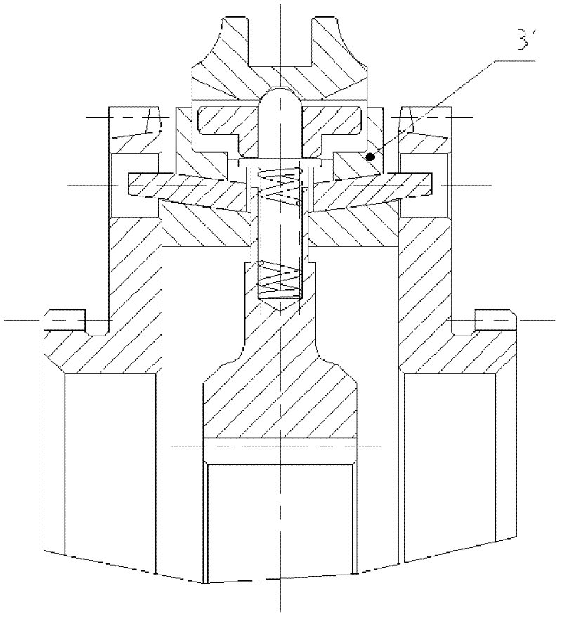
[0002] see image 3 As shown, the locking ring synchronizing device is widely used in automobile transmissions and other fields. In its basic structure, the friction ring 3' mostly has locking teeth distributed in the circumferential direction. The friction ring with this structure has high manufacturing cost and low yield. Low

Method used


Image

  • Lock ring type synchronization device and its synchronization method
  • Lock ring type synchronization device and its synchronization method
  • Lock ring type synchronization device and its synchronization method

Examples


Embodiment Construction

[0028] The present invention will be described in further detail below in conjunction with the accompanying drawings.

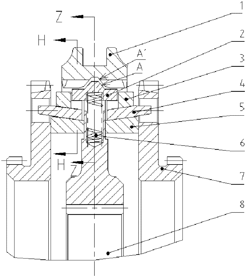
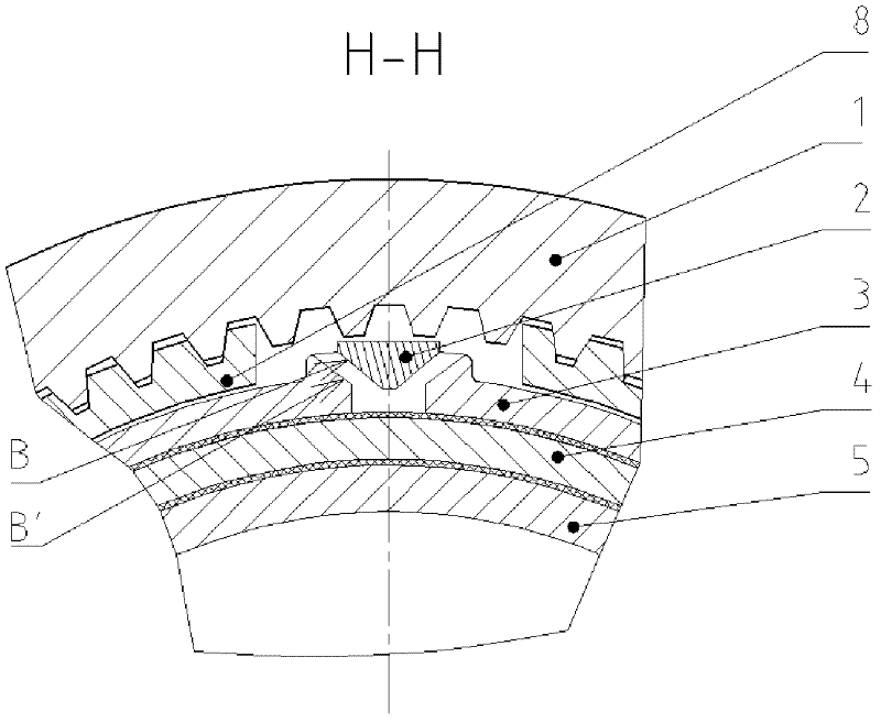
[0029] figure 1 A typical embodiment of the invention is presented. The synchronization device includes a sliding sleeve 1 , a stop block 2 , a friction ring 3 , an intermediate ring 4 , an inner friction ring 5 , a spring 6 , a combined ring gear 7 and a gear hub 8 .

[0030] The sliding sleeve 1 of the present invention has several locking grooves distributed in the circumferential direction, and the locking grooves are matched with the stop block 2. At the same time, the stop block 2 is embedded in several grooves on the gear hub 8. The shape of the groove and The dimensions ensure that the stop block 2 can move axially. The locking groove of the sliding sleeve 1 has a slope A', and the two sides of the top of the stop block 2 are provided with slopes A matched with the slope A'. There is also another group of inclined surfaces B on the stop block 2, a...


PUM


Abstract

The invention provides a lock ring type synchronization device and its synchronization method. The synchronization device comprises a slide sleeve, a first friction ring, a second friction ring, a combination toothed ring and a gear hub. On the gear hub are inlaid plural stoppers capable of moving axially; the slide sleeve is arranged at the periphery of the gear hub; plural locking grooves fitted with the stoppers are distributed on the circumferential direction of the slide sleeve; the first friction ring rotates along with the gear hub; the second friction ring and the combination toothed ring rotate together; the first friction ring is arranged at the periphery of the second friction ring and the opposite faces of the first and second friction rings are a pair of matching oblique planes; the first friction ring is provided with a groove having a first oblique plane, and the side wing of the stopper is provided with a second oblique plane matching with the first oblique plane; the locking groove of the slide sleeve has a third oblique plane and a fourth oblique plane matching with the third oblique plane is arranged at two sides of the top of the stopper; and the first friction ring is provided with a locking tooth. According to the invention, process precision requirements and costs are lowered, gear shift noise is low and reliability is high.

Description

【Technical field】 [0001] The invention relates to the field of motor vehicle transmission and control, in particular to a lock-ring type synchronizing device and a synchronizing method thereof. 【Background technique】 [0002] see image 3 As shown, the locking ring synchronizing device is widely used in automobile transmissions and other fields. In its basic structure, the friction ring 3' mostly has locking teeth distributed in the circumferential direction. The friction ring with this structure has high manufacturing cost and low yield. Low. [0003] When the synchronizer with locking teeth is locked, impact and friction will be generated on the locking surface, resulting in shifting noise. [0004] With the increase of raw material cost and processing cost and the improvement of people's noise requirements, how to reduce the production cost of the synchronizer friction ring and improve its performance has become more and more urgent. 【Content of invention】 [0005] Th...

Claims


Application Information

Patent Timeline
IPC IPC(8): F16H57/00
Inventor 张发勇郭增钢
Owner SHAANXI FAST GEAR CO
Learn More