
Bicycle front derailleur

a front derailleur and bicycle technology, applied in mechanical equipment, transportation and packaging, gearing, etc., can solve the problems of difficult clamping of the prior front derailleur at the proper location, poor positioning/orientation, and inability to adjust the position of the front derailleur, so as to achieve smooth shifting of the chain

Inactive Publication Date: 2010-01-26
SHIMANO INC
View PDF10 Cites 25 Cited by
  • Summary
  • Abstract
  • Description
  • Claims
  • Application Information

AI Technical Summary

Benefits of technology

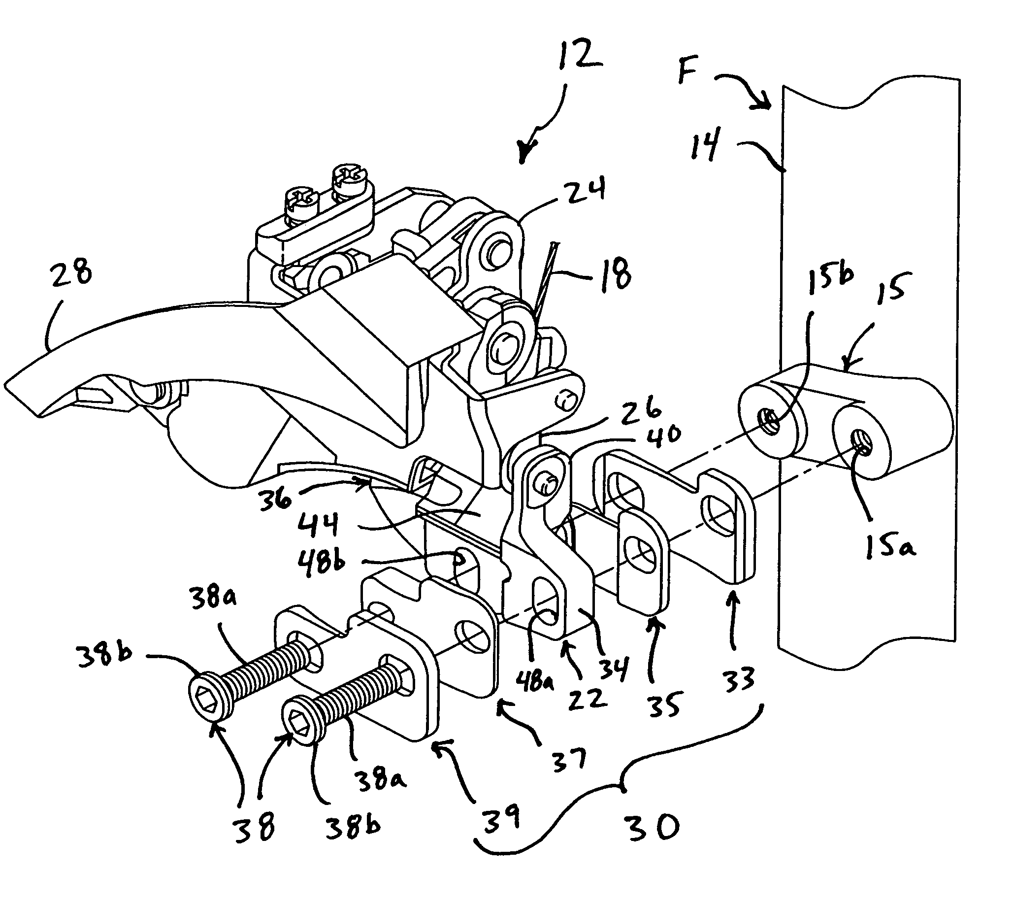
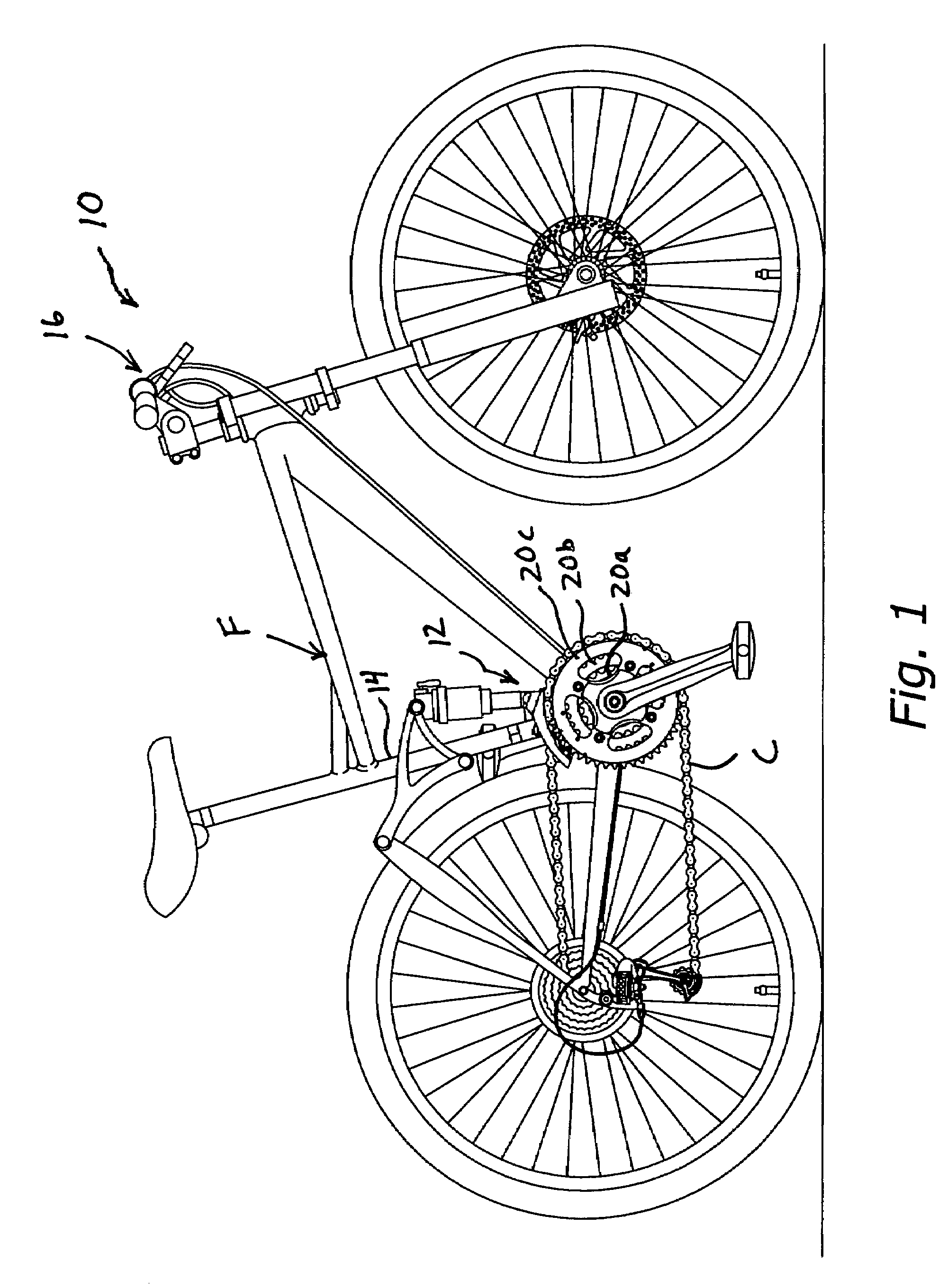
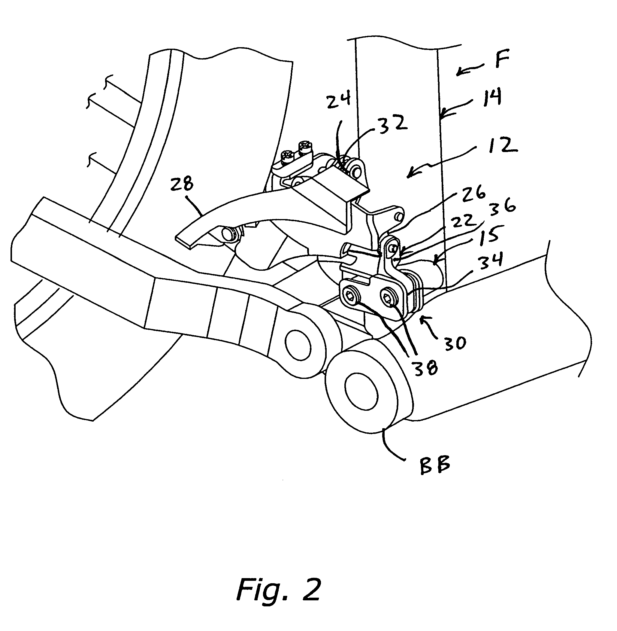
The present invention provides a bicycle front derailleur that can smoothly shift a chain between multiple front sprockets or rings. It is designed to be easily mounted in an adjustable manner to a seat tube using a fastener and is relatively simple and inexpensive to manufacture, assemble, and attach to the bicycle frame. The derailleur includes a fixed member, a chain guide, a linkage assembly, and a mounting fixture. The chain guide moves between a retracted and extended position relative to the fixed member, and the linkage assembly moves the chain guide between the positions. The mounting fixture is securely attached to the fixed member and includes a frame fastener and washer members.

Problems solved by technology

While these front derailleurs generally work well, because they are clamped onto the seat tube, the position / orientation may not be optimal (i.e., shifting performance may not be optimal).
In other words, it can be difficult to clamp these prior front derailleurs at the proper location.
Moreover, it is possible for these types of front derailleurs to sometimes move slightly during use, due to a loosened fastener, repeated vibrations and / or contact with an obstruction or the like.
However, it is possible that during manufacture of bicycle frames with such permanent derailleur mounting portions for some variance in the various bicycle frames on the production line.
Accordingly, even when a permanent (i.e., welded or brazed-on) derailleur mounting portion fixed to the seat tube is utilized, the position / orientation may not be optimal (i.e., shifting performance may not be optimal).

Method used


Image

  • Bicycle front derailleur
  • Bicycle front derailleur
  • Bicycle front derailleur

Examples


second embodiment

[0095]Referring now to FIGS. 25-48, a bicycle front derailleur 212 in accordance with a second embodiment of the present invention will now be explained. The bicycle front derailleur 212 of this second embodiment is identical to the front derailleur 12 of the first embodiment, except that the front derailleur 212 of this second embodiment includes a modified mounting fixture 230. Specifically, the modified mounting fixture 230 of this second embodiment includes modified washer members 233, 235, 237 and 239.

[0096]In view of the similarity between the first and second embodiments, the parts of the second embodiment that are identical to the parts of the first embodiment will be given the same reference numerals as the parts of the first embodiment. Also, parts of this second embodiment that are functionally identical and / or substantially identical to parts of the first embodiment will be given the same reference numerals but with “200” added thereto. In any event, the descriptions of ...


PUM


Abstract

A bicycle front derailleur includes a fixed member, a chain guide, a linkage assembly and an adjustable mounting fixture. The fixed member includes a frame mounting portion having at least one frame mounting hole and a linkage support portion. The linkage assembly is coupled between the linkage support portion and the chain guide in order to move the chain guide between the retracted position and the extended position. The mounting fixture is adjustably coupled to the fixed member. The mounting fixture including at least one frame fastener disposed in the frame mounting hole, a pair of first washer members disposed on a first side of the frame mounting portion and a pair of second washer members disposed on a second side of the frame mounting portion with the frame fastener extending through the first and second washer members.

Description

BACKGROUND OF THE INVENTION[0001]1. Field of the Invention[0002]This invention generally relates to a bicycle front derailleur. More specifically, the present invention relates to a bicycle front derailleur, which is designed to be attached to a seat tube of a bicycle frame and which includes a mounting fixture adjustably coupled to the fixed member to adjust the angular orientation / position of the chain guide relative to the frame.[0003]2. Background Information[0004]Bicycling is becoming an increasingly more popular form of recreation as well as a means of transportation. Moreover, bicycling has become a very popular competitive sport for both amateurs and professionals. Whether the bicycle is used for recreation, transportation or competition, the bicycle industry is constantly improving the various components of the bicycle. One component that has been extensively redesigned is the bicycle front derailleur.[0005]Generally, a front derailleur includes a fixed member non-movably s...

Claims


Application Information

Patent Timeline
Patent Type & Authority Patents(United States)
IPC IPC(8): B62M9/12B62M9/1342B62M9/135
CPCB62M9/135B62M9/1342
Inventor YAMAMOTO, KAZUFUMIFUJII, NOBUYOSHINANKOU, YOSHIAKI
Owner SHIMANO INC
Learn More