Firearm frame with configurable grip

a technology of configurable grips and firearms, applied in the field of firearm grips, can solve the problems of weight and thickness of the grip, the user being forced to alter the manual grip or hold, the use of tools generally complicating the process, etc., and achieve the effect of relative ease and facilitate the registration of the backstrap

Active Publication Date: 2006-07-13
SMITH & WESSON
View PDF99 Cites 20 Cited by
  • Summary
  • Abstract
  • Description
  • Claims
  • Application Information

AI Technical Summary

Benefits of technology

[0007] In an additional embodiment, one advantage of the present invention is that the handgun grip, particularly a removable portion thereof (e.g. the backstrap, also called the “gripstrap”), can be selected by the user based on the user's preference. Backstraps of various forms, thicknesses, and textures can be fitted to a handgun depending upon if the handgun is to be used for target shooting, competitive target shooting, hunting, personal protection, or any other shooting activity.
[0008] In an additional embodiment, another advantage of the present invention is that the removable grip portion, (e.g. the backstrap) can be removed and installed without the use of tools. Cooperative portions on the inner surfaces of the backstrap and the rearward portion of the grip facilitate the registration of the backstrap with the frame in preparation for the insertion of a locking element, typically a pin. Thus, a user can secure the backstrap in place on the frame of the handgun with one hand and with relative ease and insert the locking pin through the backstrap and into the frame with the other hand.

Problems solved by technology

However, modifications made by such a method generally add weight and thickness to the grip, thereby forcing the user to alter his manual grip, or hold, on the firearm.
The use of tools generally complicates the process by which the grip portions are changed.

Method used


Image

  • Firearm frame with configurable grip
  • Firearm frame with configurable grip
  • Firearm frame with configurable grip

Examples


Embodiment Construction

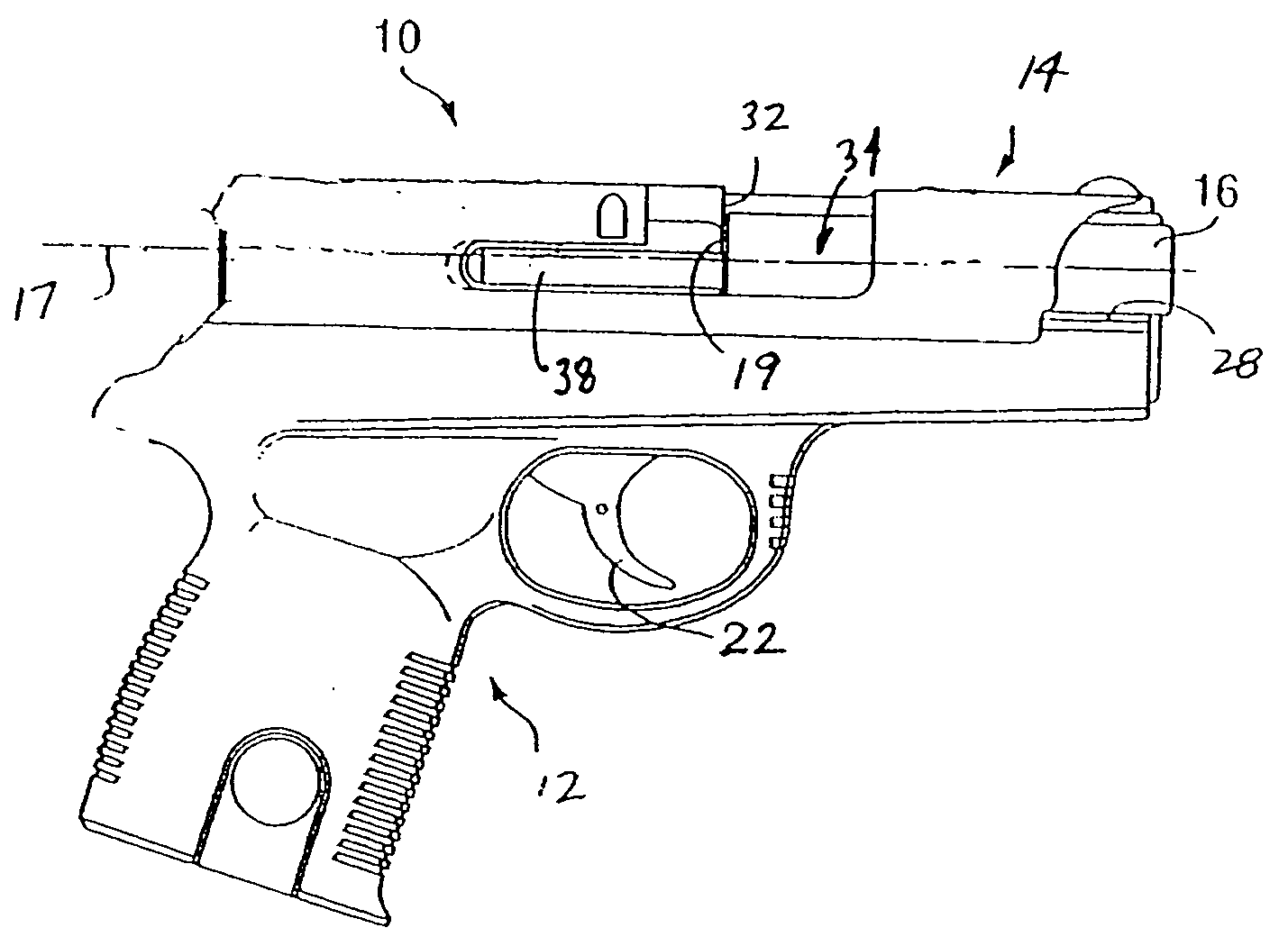
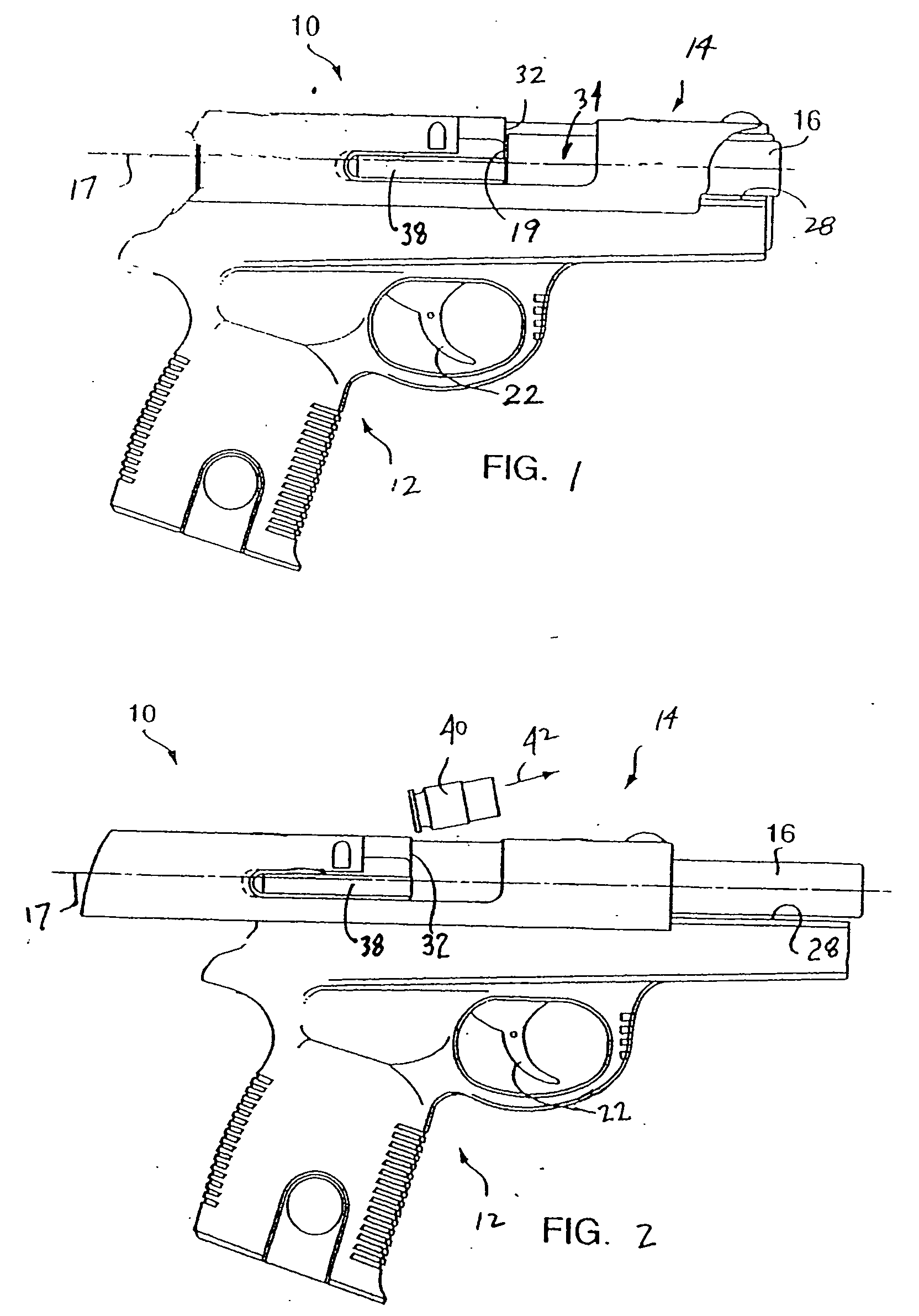
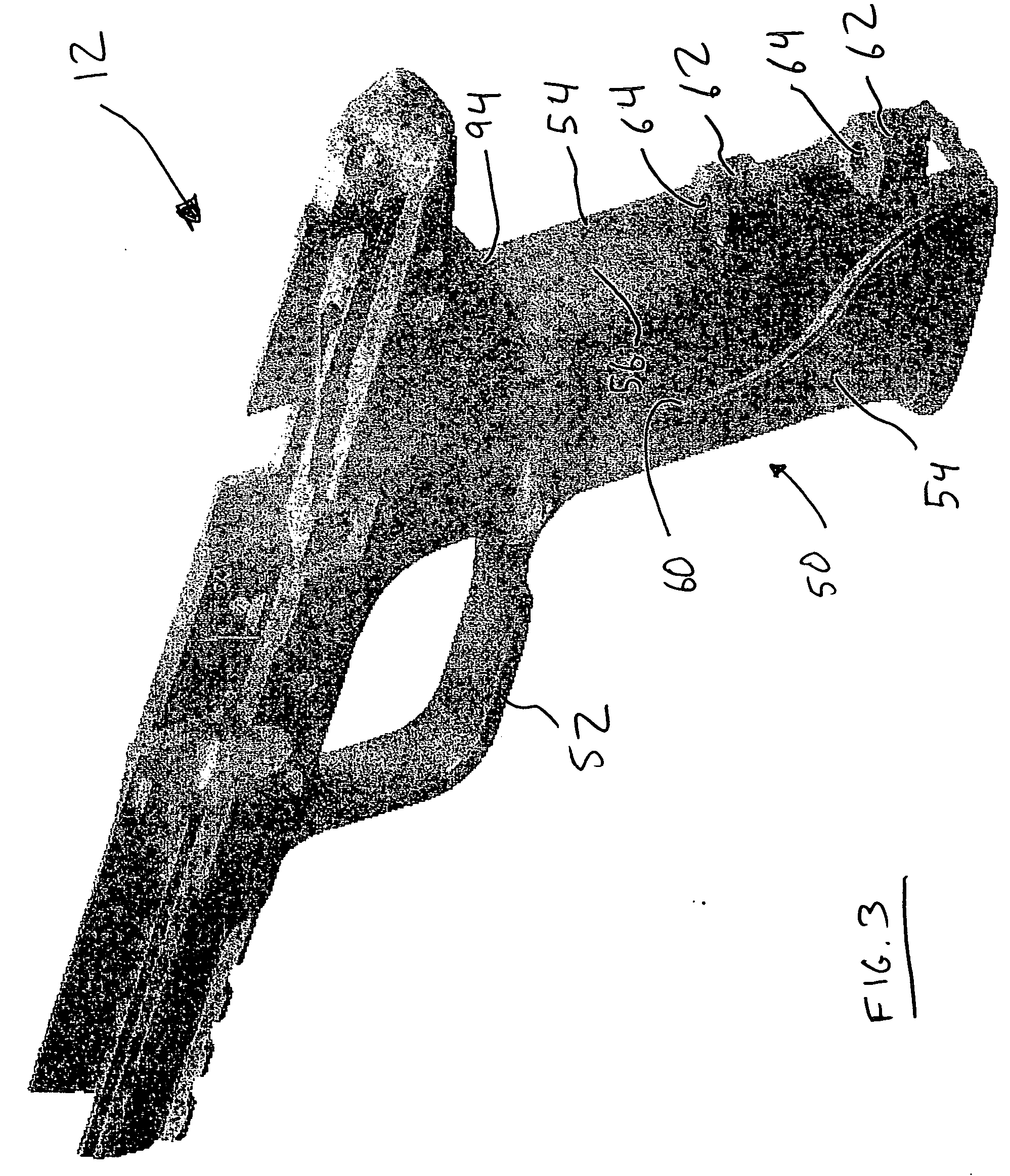
[0016] Referring to FIGS. 1 and 2, a semiautomatic pistol or handgun is shown generally at 10 and is hereinafter referred to as “handgun 10.” The handgun 10 comprises a frame 12, a slide 14, and a fire control mechanism that operates via actuation of a trigger 22. The frame 12 is fabricated of a high-impact polymer material, metal, or a combination of polymer and metal. The slide 14 houses a barrel 16 in the forward end thereof. The barrel 16 is cooperatively linked with the slide 14 and, together with the slide 14, defines a longitudinal firing axis 17. A rearward end 19 of the barrel 16 is adapted for receiving an ammunition cartridge.

[0017] The slide 14 is fitted to opposingly-positioned rails 28 on the frame 12 to effect the reciprocal movement of the slide 14 along the longitudinal firing axis 17. The rails 28 extend along the underside of the slide 14 in the longitudinal direction and are cooperative with the frame 12 to allow the cycling of the slide 14 between forward (batt...


PUM


Abstract

A configurable firearm grip is provided in which a removable portion thereof can be selected by the user based on the user's preference. For example, backstraps of various forms, thicknesses, and textures can be fitted to a handgun depending upon if the handgun is to be used for target shooting, competitive target shooting, hunting, personal protection, or any other shooting activity, or to accommodate varying hand sizes. The backstrap can be removed and installed without the use of tools. Cooperative portions on the inner surfaces of the backstrap and the rearward portion of the grip facilitate the registration of the backstrap with a fixed portion in preparation for the insertion of a locking element. The backstrap is able to be secured on the fixed grip portion of the handgun with one hand while the locking element is inserted through the backstrap and the fixed grip portion with the other hand.

Description

CROSS REFERENCE TO RELATED APPLICATIONS [0001] This application claims the benefit of the following U.S. Provisional Application Ser. No. 60 / 639,187; Ser. No. 60 / 638,594; Ser. No. 60 / 638,753; Ser. No. 60 / 638,593; Ser. No. 60 / 638,746; Ser. No. 60 / 638,592; Ser. No. 60 / 638,751; and Ser. No. 60 / 638,752, all filed Dec. 22, 2004, and all hereby incorporated by reference herein in their entireties.FIELD OF THE INVENTION [0002] This invention relates generally to firearm grips and, more particularly, to a firearm on which the grips can be configured at the desire of the user. BACKGROUND OF THE INVENTION [0003] The grip, or grip portion, of a handgun functions as the user physically interfaces with the handgun. Accordingly, control of the handgun is the direct result of the hand pressure that the user exerts on the grip. Because hand sizes among different users vary greatly, the grip of a handgun can be modified to accommodate various users. Moreover, it may also be desirable for a user to c...

Claims


Application Information

Patent Timeline
Patent Type & Authority Applications(United States)
IPC IPC(8): F41C23/00
CPCF41A11/02F41C23/14
Inventor POULIN, MICHAEL J.O'CLAIR, SEAN
Owner SMITH & WESSON
Why Eureka
Try Eureka