
Support for a sliding panel

Inactive Publication Date: 2006-07-13
HUNTER DOUGLAS IND BV
View PDF16 Cites 12 Cited by
  • Summary
  • Abstract
  • Description
  • Claims
  • Application Information

AI Technical Summary

Benefits of technology

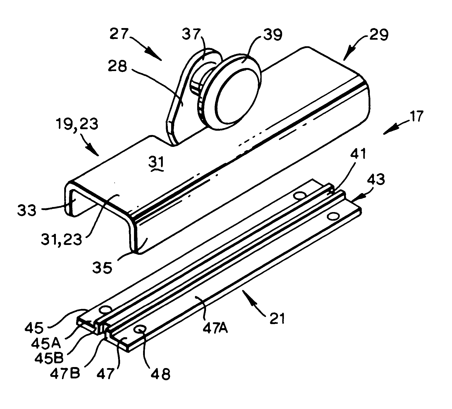
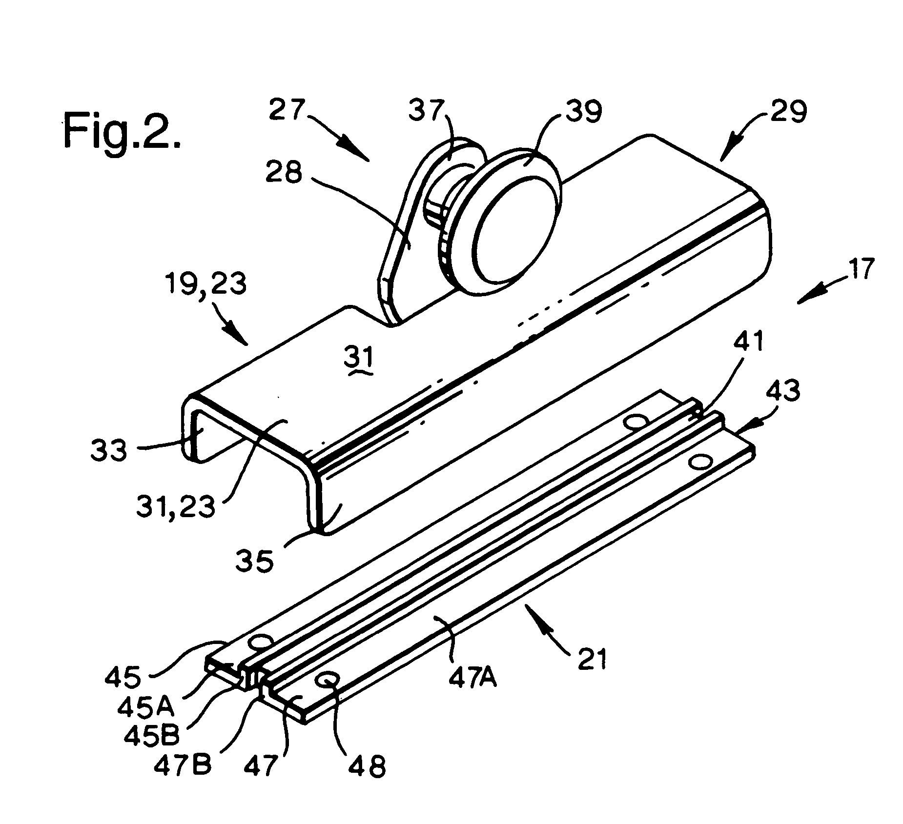
[0010] In accordance with this invention, a sliding panel is provided which is releasably connected at its top or upper edge and / or at its bottom or lower edge to a carrier that supports the panel; wherein the means for releasably connecting the panel and the carrier comprises a magnet and a ferrous member which is attracted to, and can be magnetically attached to, the magnet; and wherein the magnet is on one of either the carrier or the panel and the ferrous member is on the other of the carrier or panel. This connection makes it easier to connect and to release the panel from the carrier, while at the same time not allowing Inadvertent release of the panel from the carrier during normal operating conditions.
[0011] It is advantageous that the magnet is on the panel and the ferrous member is on the carrier. It is particularly advantageous that the carrier is entirely made from a ferrous material which is attracted to, and can be magnetically attached to the magnet.
[0012] It is also advantageous that the magnet or the ferrous member is attached to the panel in a height adjustable manner.
[0014] It is also advantageous that the carrier can slide or roll smoothly and easily along a track that supports the carrier and the panel.

Problems solved by technology

The panel cannot be easily disconnected from the carrier.
This makes the releasability less convenient than desired.
A snap connection that is strong enough to securely hold a door which is significantly heavier in weight than a light blind panel would have to be quite strong and thus will be difficult to release.

Method used


Image

  • Support for a sliding panel
  • Support for a sliding panel
  • Support for a sliding panel

Examples


Embodiment Construction

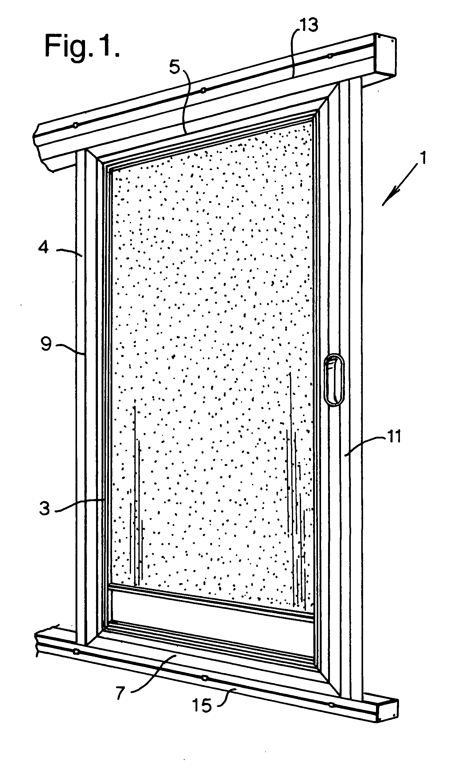
[0021]FIG. 1 shows a sliding screen door 1 having a generally rectangular screen 3 fixed in a frame 4 with top, bottom, left and right frame members 5, 7, 9, 11. The door 1 is suspended by its top frame member 5 from a top profile 13. The top profile 13 can be mounted for example parallel to, and above, the top of an architectural opening such as a door frame or the like (not shown), the length of the top profile 13 preferably being longer than the length of the top of the door frame member in order to provide the possibility of sliding the screen door panel in a position coinciding and thus closing the architectural opening and in a position away and thus opening the architectural opening. The bottom frame member 7 of the sliding screen panel is supported by a bottom profile 15 that preferably is mounted parallel to the bottom of an architectural opening such as a door frame or the like and is of equal length to the top profile 13. In this regard, the door 1 is suspended from the t...


PUM


Abstract

A sliding panel for use in an architectural opening is connected either at its top edge or bottom edge to a carrier that supports the panel with a magnetic system that includes a magnet and a ferrous member. The magnet is positioned on either the carrier or the panel and the ferrous member is on the other of the carrier or the panel with the magnet attracting the ferrous member to connect the panel to the carrier.

Description

CROSS REFERENCE TO RELATED APPLICATION [0001] This application claims priority to European patent application No. 05075027.2, filed 07 Jan. 2005, which is hereby incorporated by reference as if fully disclosed herein. BACKGROUND OF THE INVENTION [0002] 1. Field of the Invention [0003] The invention relates to a sliding panel, such as a vertical venetian blind panel, a wall hanging, a solid door or a screen door, which is releasably connected, at its top or upper edge or at its bottom or lower edge, to a carrier that can slide or roll smoothly and easily along a track that supports the panel. [0004] 2. Description of the Related Art [0005] Sliding panels are known, for example from GB 2 001 120, U.S. Pat. No. 3,261,129 and U.S. Pat. No. 3,925,933. A sliding door generally is provided at its top or upper edge with moving means such as wheels, rollers, runners, sliding blocks or the like that can slide or roll along a track. The sliding door with its moving means depends from a track t...

Claims


Application Information

Patent Timeline
IPC IPC(8): E05D15/06
CPCE05D15/0626E05D15/063E05D15/0652E05Y2201/64E05Y2201/702E05Y2600/20E05Y2201/46E05Y2201/418
Inventor VAN 'T ZELFDE, ADRIANUS JACOBSLOBBE, CHRISTIANUS WILFRED MICHAEL
Owner HUNTER DOUGLAS IND BV
Learn More