Weather protection system

a technology of weather protection and system, applied in the field of weather protection system, can solve the problems of major damage to, and even destruction of, structures, residential houses, commercial buildings, etc., and achieve the effect of efficient and protective manner

Inactive Publication Date: 2006-07-13
HOGG THOMAS W JR +1
View PDF7 Cites 6 Cited by
  • Summary
  • Abstract
  • Description
  • Claims
  • Application Information

AI Technical Summary

Benefits of technology

[0013] It is, therefore, an object of the preferred embodiment of this invention to provide a facility for placement of a protective cover, and ont, a structure in an efficient and protective manner.

Problems solved by technology

Storms of this nature have led to major damage to, and even the destruction of, structures, such as residential houses, trailers, commercial buildings, and the like, which are located in the path of such storms.
While such adverse weather conditions develop, and are encountered, in many parts of the world, their destructive forces are particularly prevalent in the island countries located in the Caribbean Sea, and portions of countries which border the contiguous waters of the Caribbean Sea, the Gulf of Mexico, and the northwestern shoreline of the Atlantic Ocean.
Several states along the southern and eastern border of the United States of America are frequently subjected to such adverse weather conditions.
It is well known that, for many years, storms of this nature have caused widespread structural devastation, resulting in personal tragedies including homelessness, injury and even death.
However, each of the group of five patents do not disclose any facility for placing the cover over the structure.
However, the system does not show any facility for placement of the cover onto the structure, or for securance of the edges of the cover.
With continued operation of the winches, the cables, including the portions attached to the sides of the netting, are drawn tighter by the cable reels resulting in forced downward movement of the poles to the collapsed position, and a tensioning of the netting around the structure.
Also, while the system shows securance of the netting at the netting reel, the cable reels and adjacent the winches, the system does not show facility for securance of other portions of the edges of the netting.
Thus, there is a need for an unobtrusive, uncomplicated weather protection system which readily facilitates placement of a protective cover over, and onto, a structure in an efficient and protective manner.

Method used


Image

  • Weather protection system
  • Weather protection system
  • Weather protection system

Examples


Embodiment Construction

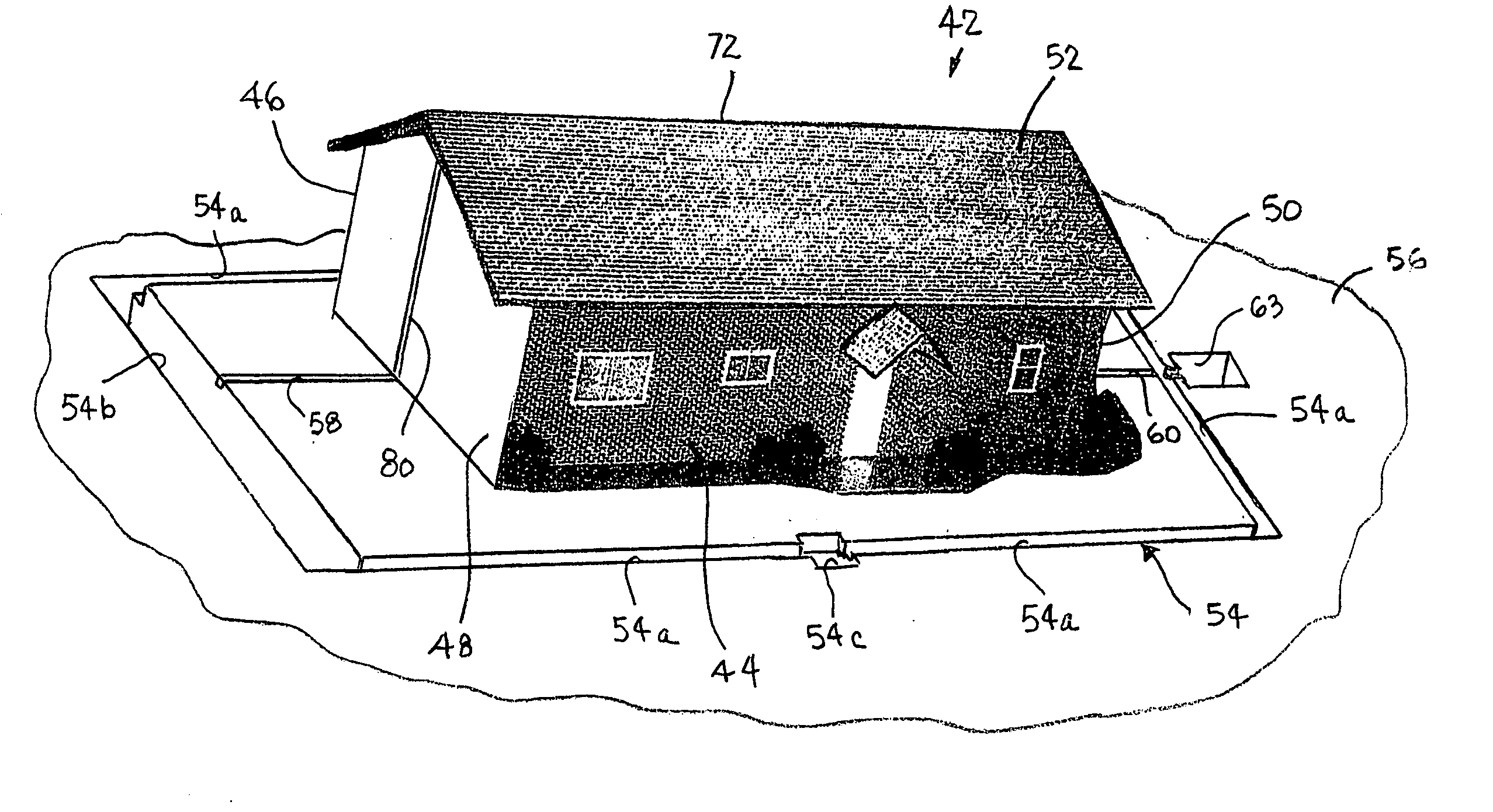
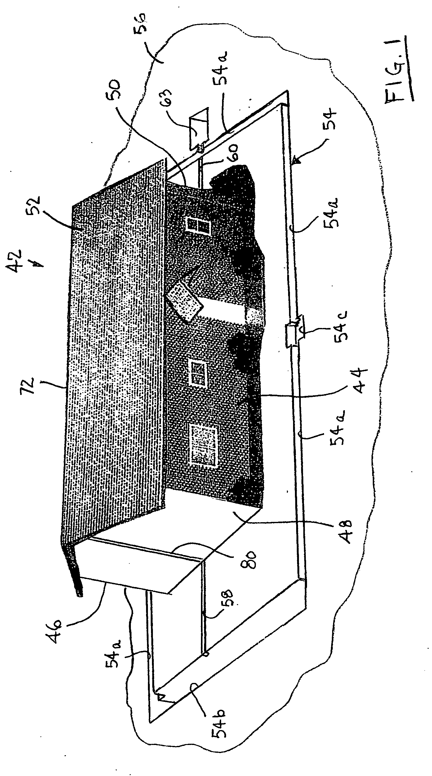
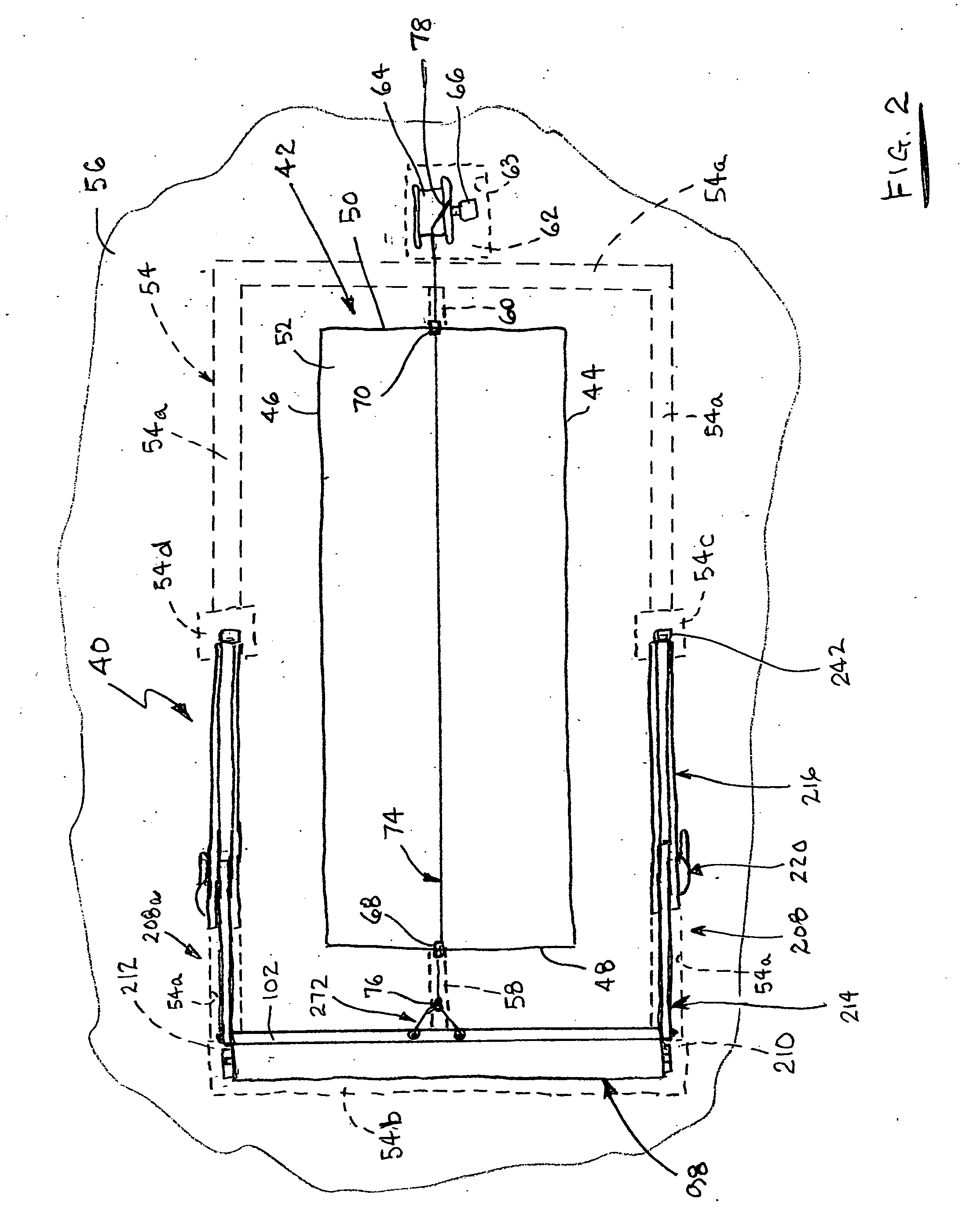
[0058] A weather protection system 40, as illustrated in FIGS. 2 and 20 through 24, provides a protective wind and rain shield for a structure 42, as illustrated in FIGS. 1, 2 and 20 through 24, in the presence of violent and destructive weather of the type which typically occurs during adverse weather conditions, such as, for example, hurricanes, tornados, cyclones, and the like. The structure 42 to be protected, as illustrated in FIGS. 1, 2 and 20 through 24, is a residential dwelling. However, the weather protection system 40 can be used to provide a protective shield for other types of structures, such as, for example, trailers, apartment buildings, office buildings, warehouse buildings, manufacturing buildings, and the like, without departing from the spirit and scope of the invention.

[0059] Referring further to FIGS. 1 and 2, the exterior of the structure 42 is formed with a front wall 44, a rear wall 46, a right side wall 48, a left side wall 50, and a roof 52. In preparatio...


PUM


Abstract

A protective cover 98 is stored adjacent a right side wall 48 of a structure 42 for use in protecting the structure during adverse weather conditions. A cable 74 is attached to a bar 102 at a leading portion of the cover 98. The cable 74 extends over a roof 52 of the structure 42, and is attached to a reel 64 adjacent a left side wall 50. Lift arms 208 and 208a are located adjacent a front and rear wall, respectively, for pivoting movement about intermediate sections of the front and rear walls. The lift arms 208 and 208a are coupled to the bar 102. As the reel 64 is operated, the cover 98 is pulled toward the structure 42, and the lift arms 208 and 208a raise the cover above the structure.

Description

[0001] This application claims the benefit of U.S. Provisional Application No. 60 / 642,552 filed Jan. 11, 2005, which is incorporated herein by reference thereto.BACKGROUND OF THE INVENTION [0002] This invention relates to a weather protection system, and relates particularly to a system for shielding a structure during adverse weather conditions. [0003] It is commonplace for severe wind and rain storms, such as hurricanes, tornadoes, cyclones and the like, to develop in areas of tropic, or near tropic, temperatures. Storms of this nature have led to major damage to, and even the destruction of, structures, such as residential houses, trailers, commercial buildings, and the like, which are located in the path of such storms. While such adverse weather conditions develop, and are encountered, in many parts of the world, their destructive forces are particularly prevalent in the island countries located in the Caribbean Sea, and portions of countries which border the contiguous waters ...

Claims


Application Information

Patent Timeline
Patent Type & Authority Applications(United States)
IPC IPC(8): E06B1/04B62D63/04
CPCE04H9/14Y02A50/00
Inventor HOGG, THOMAS W. JR.DUGAN, CHRISTOPHER M.
Owner HOGG THOMAS W JR
Why Eureka
Try Eureka