Method and system for electronic compass calibration and verification

a technology of electronic compass and calibration equipment, applied in the field of electronic compass calibration and verification, can solve the problem of burden of using calibration equipment external to the magnetic compass during the calibration of the magnetic compass

Active Publication Date: 2006-07-13
HONEYWELL INT INC
View PDF0 Cites 38 Cited by
  • Summary
  • Abstract
  • Description
  • Claims
  • Application Information

AI Technical Summary

Problems solved by technology

The need to use calibration equipment external to a magnetic compass during the calibration of a magnetic compass may be a burden to

Method used


Image

  • Method and system for electronic compass calibration and verification
  • Method and system for electronic compass calibration and verification
  • Method and system for electronic compass calibration and verification

Examples


Embodiment Construction

1. Magnetic Compass Overview

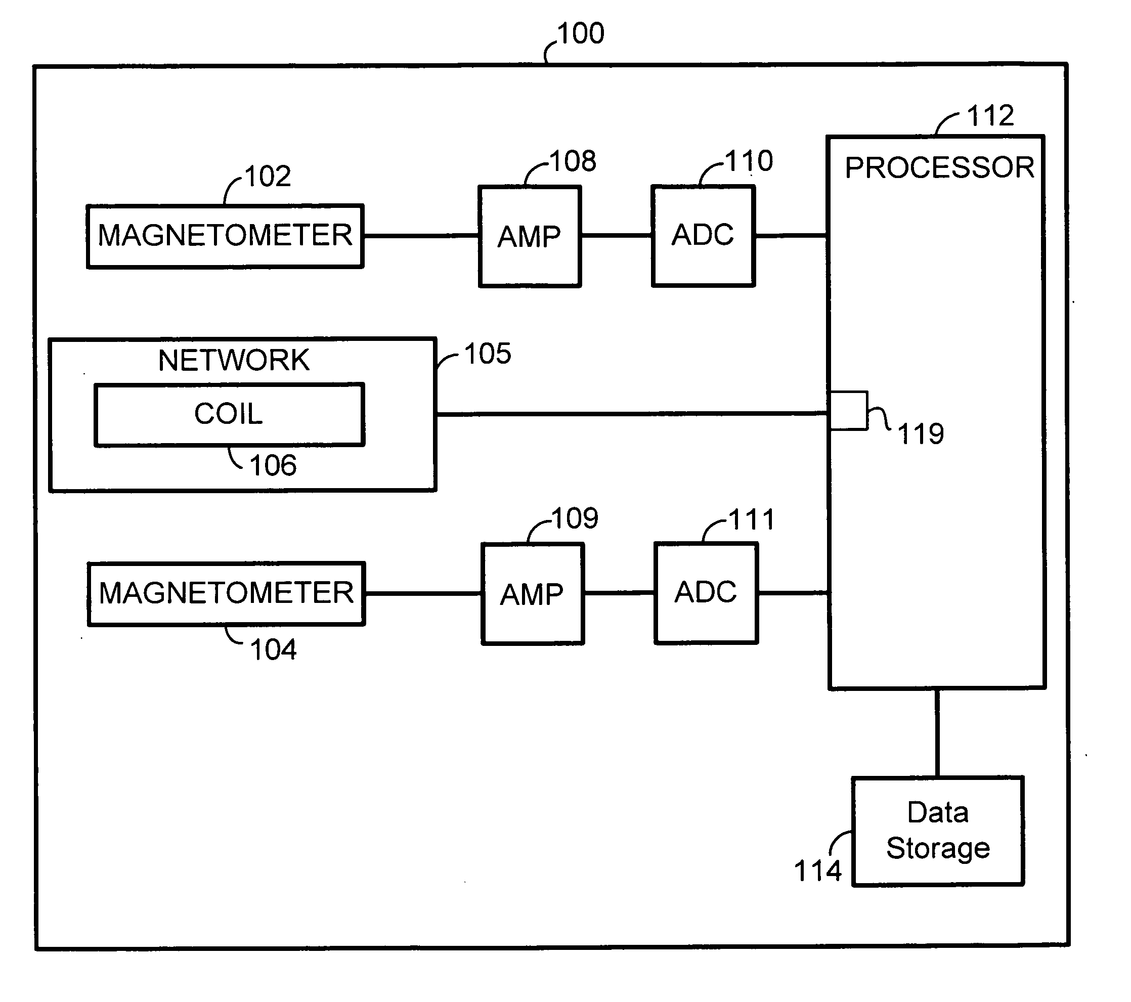
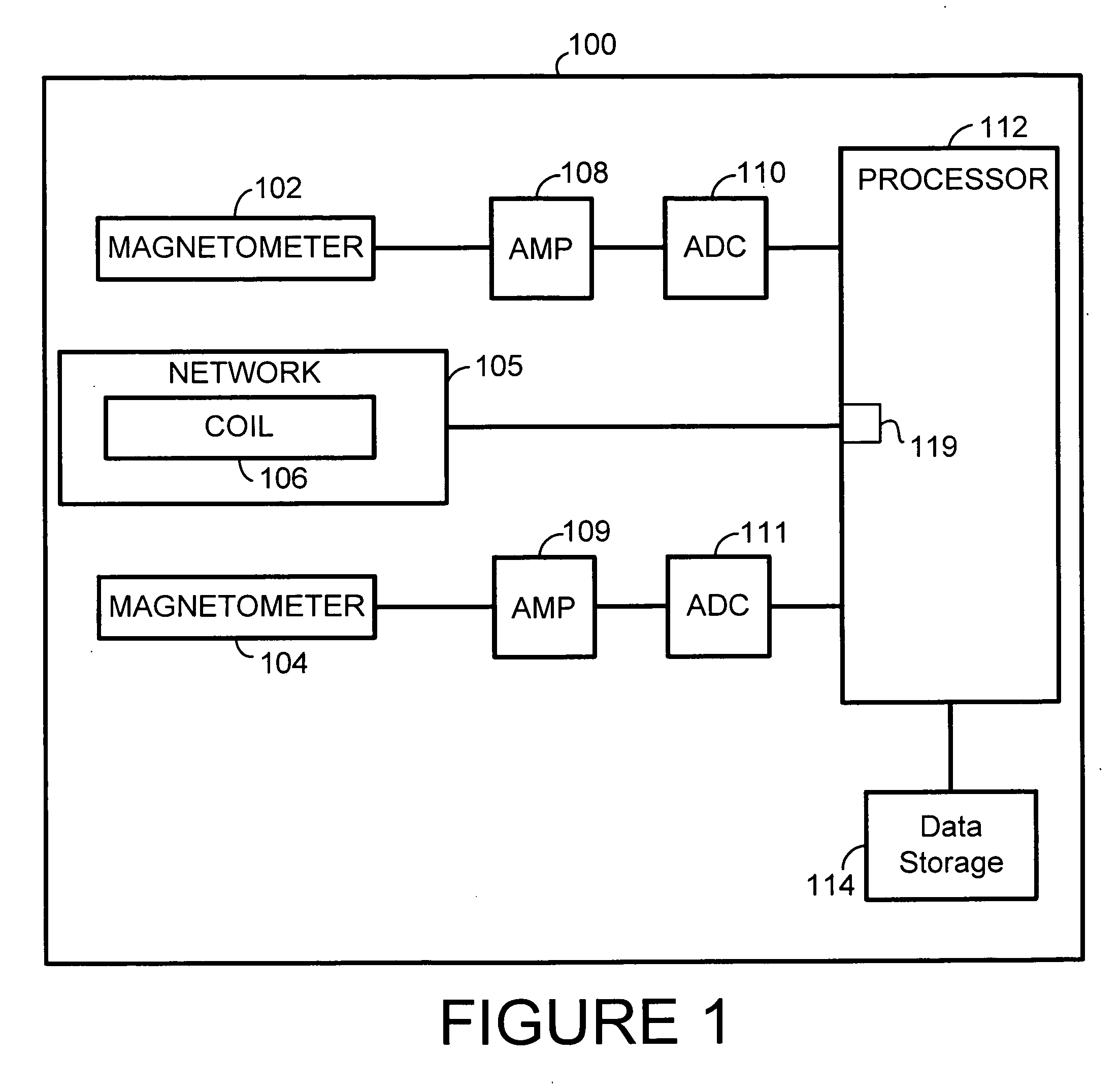
[0026]FIG. 1 is a block diagram of a magnetic compass 100 arranged in accordance with a preferred embodiment of the present invention. The magnetic compass 100 includes: (i) magnetometers 102, 104, (ii) a network 105 comprising a coil 106, (iii) amplifiers 108, 109, (iv) analog-to-digital converters 110, 111, (v) a processor 112, and (vi) data storage 114.

[0027] Various types of magnetometers are available for use with the present invention. For example, the magnetometers 102, 104 could each be the type of magnetometer that comprises (i) a magnetoresistive magnetic sensor, or (ii) a flux gate magnetic sensor, or (iii) a Hall-effect magnetic sensor, or (iv) some other type of magnetic sensor. Preferably, the same type of magnetometer is used for magnetometer 102 and 104. Although, FIG. 1 only shows two magnetometers, the magnetic compass 100 could include more than two magnetometers.

[0028] The magnetometers 102 and 104 sense a magnetic field (i.e. one ...


PUM


Abstract

A method and system for calibrating a magnetic compass and/or verifying a compass calibration, using a calibration magnetic field produced by a field-generating coil within the magnetic compass is described. The field-generating coil is located near magnetometers within the magnetic compass. Passing a self-trimming current through the coil produces a magnetic field that acts on the magnetometers. Samples of an output signal from each magnetometer are taken to obtain digital values that indicate the output signal from each magnetometer. The digital values are used by a processor to determine one or more calibration coefficient for using calibrating the magnetic compass. The samples of the output signals are taken when a self-trimming current is passing through the coil and when the self-trimming current is not passing through the coil. Calibration of the compass occurs by applying the one or more calibration coefficients to subsequent signals that indicate the output signals of one or more of the magnetometers.

Description

BACKGROUND [0001] 1. Field of Invention [0002] This invention relates generally to electronic compasses and more particularly to a system and method for calibrating a magnetic compass. [0003] 2. Description of Related Art [0004] Electronic compasses provide compassing capabilities in a variety of applications such as automobiles, airplanes, boats, and personal handheld devices. Magnetic compasses are one type of electronic compass that provide a means for determining a compass heading. As examples, the compass heading may indicate North or South. Other examples of compass headings are also possible. [0005] A magnetic compass may include two or more magnetometers. A magnetometer is a device capable of sensing a magnetic field or a component of a magnetic field in one or more directions. A magnetic compass may use magnetometers to sense a magnetic field in proximity to the magnetic compass and to determine a compass heading. [0006] A magnetic compass may be calibrated in order to ensu...

Claims


Application Information

Patent Timeline
IPC IPC(8): G01R33/02
CPCG01C17/38
Inventor WITHANAWASAM, LAKSHMAN S.
Owner HONEYWELL INT INC
Why Eureka
Try Eureka