Calibrating real and virtual views

a virtual and real-time calibration technology, applied in the field of augmented reality, can solve the problems of user's head jitter, inability to precisely align virtual and real markers, and hampered alignmen

Active Publication Date: 2006-07-13
SIEMENS MEDICAL SOLUTIONS USA INC
View PDF5 Cites 100 Cited by
  • Summary
  • Abstract
  • Description
  • Claims
  • Application Information

AI Technical Summary

Benefits of technology

[0012] An augmented reality system comprises a real reference generator for displaying a real reference on a calibration screen, an optical see-through display having a fixed position with respect to the real reference generator and a virtual reference generator for displaying a virtual reference on the optical see-through display. The augmented reality system further comprises an input device for aligning a view of the virtual reference with a view of the real reference through the optical see-through display, wherein the virtual reference is moved on the optical see-through display, and a processor for determining one or more parameters for rendering a virtual object as part of a real scene seen through the optical see-through display.

Problems solved by technology

This alignment is hampered by the user's head jitter.
Due to head jitter the location of the real marker jitters, and it is not possible to precisely align virtual and real markers.

Method used


Image

  • Calibrating real and virtual views
  • Calibrating real and virtual views
  • Calibrating real and virtual views

Examples


Embodiment Construction

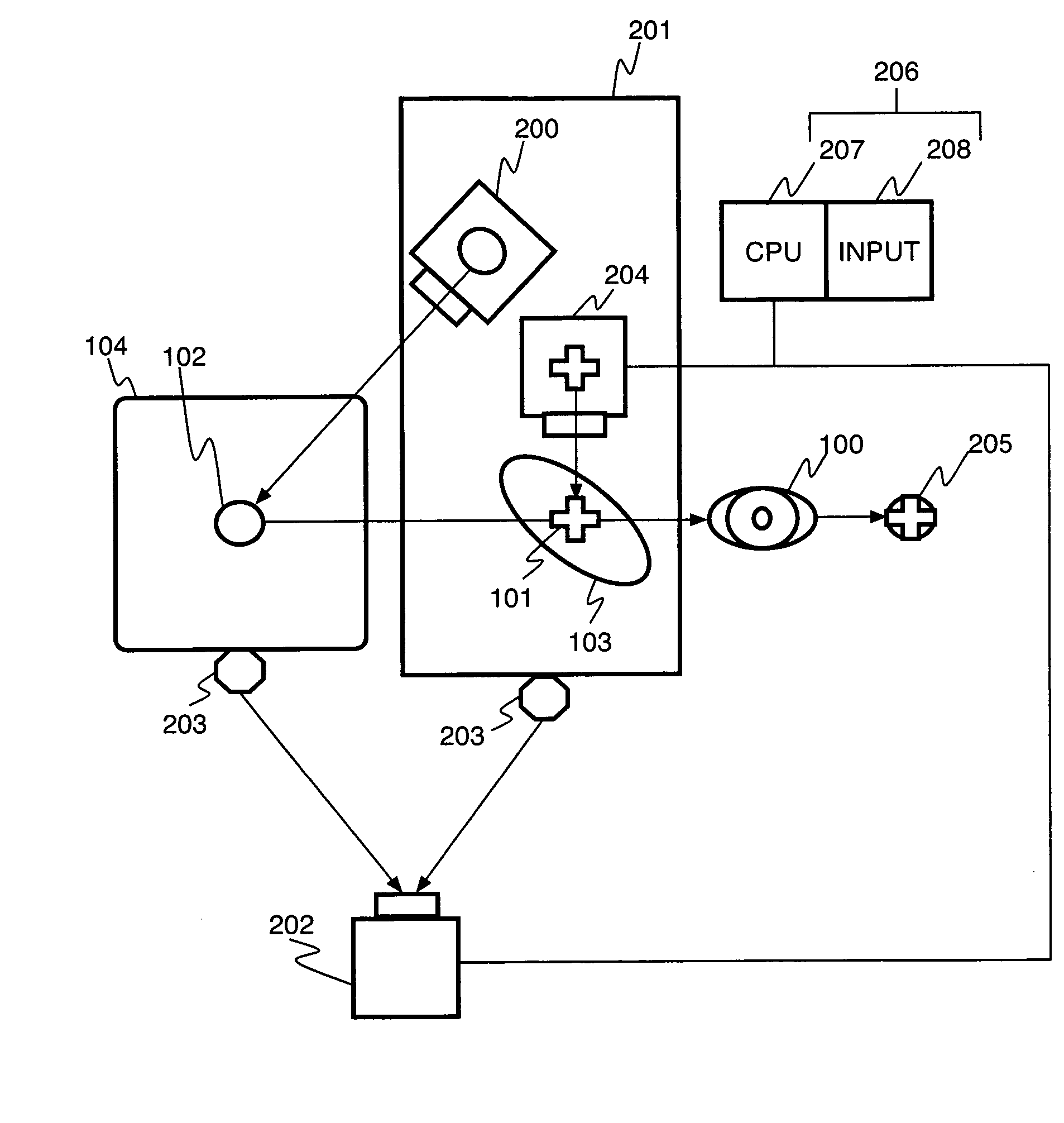
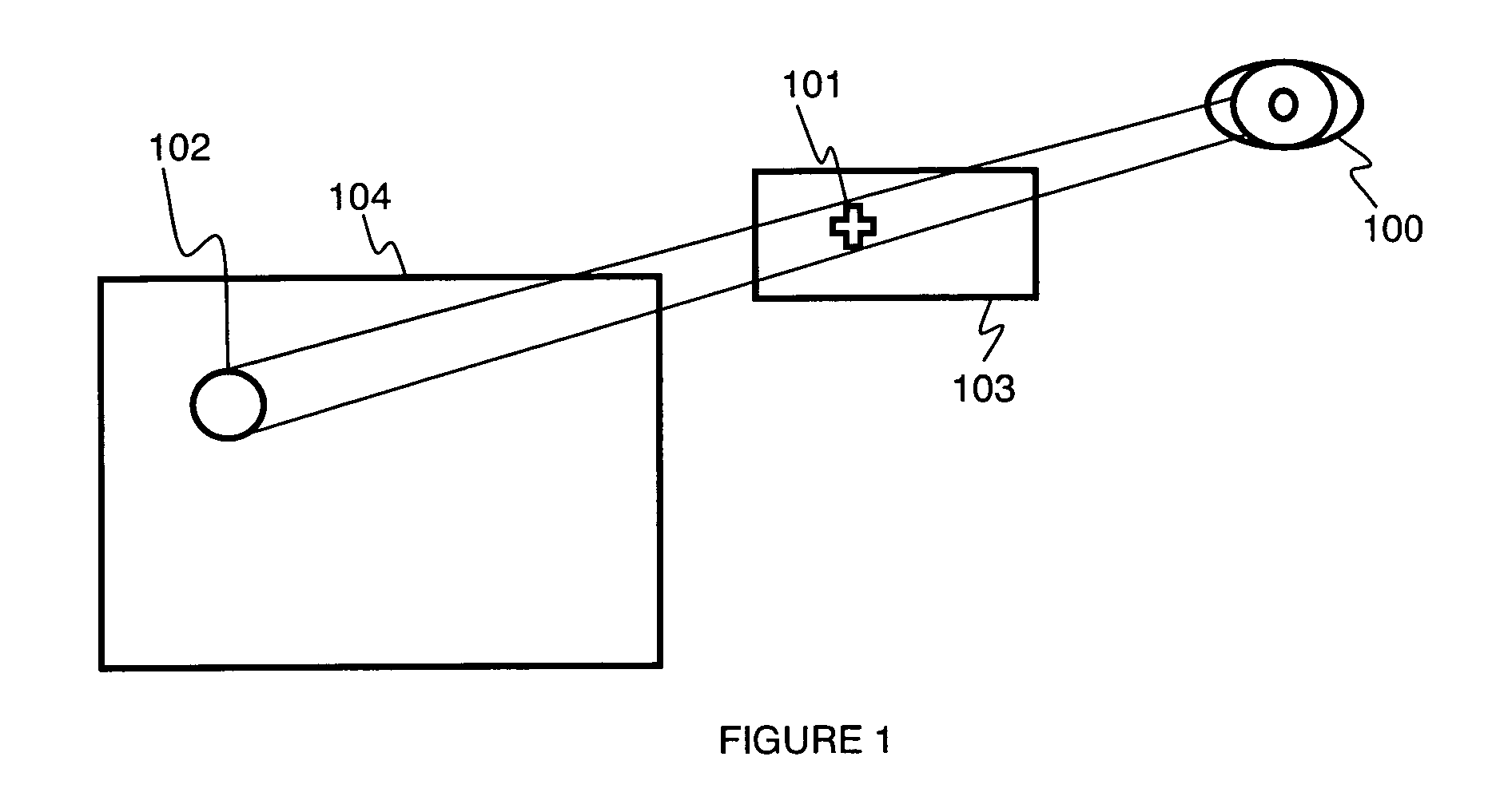
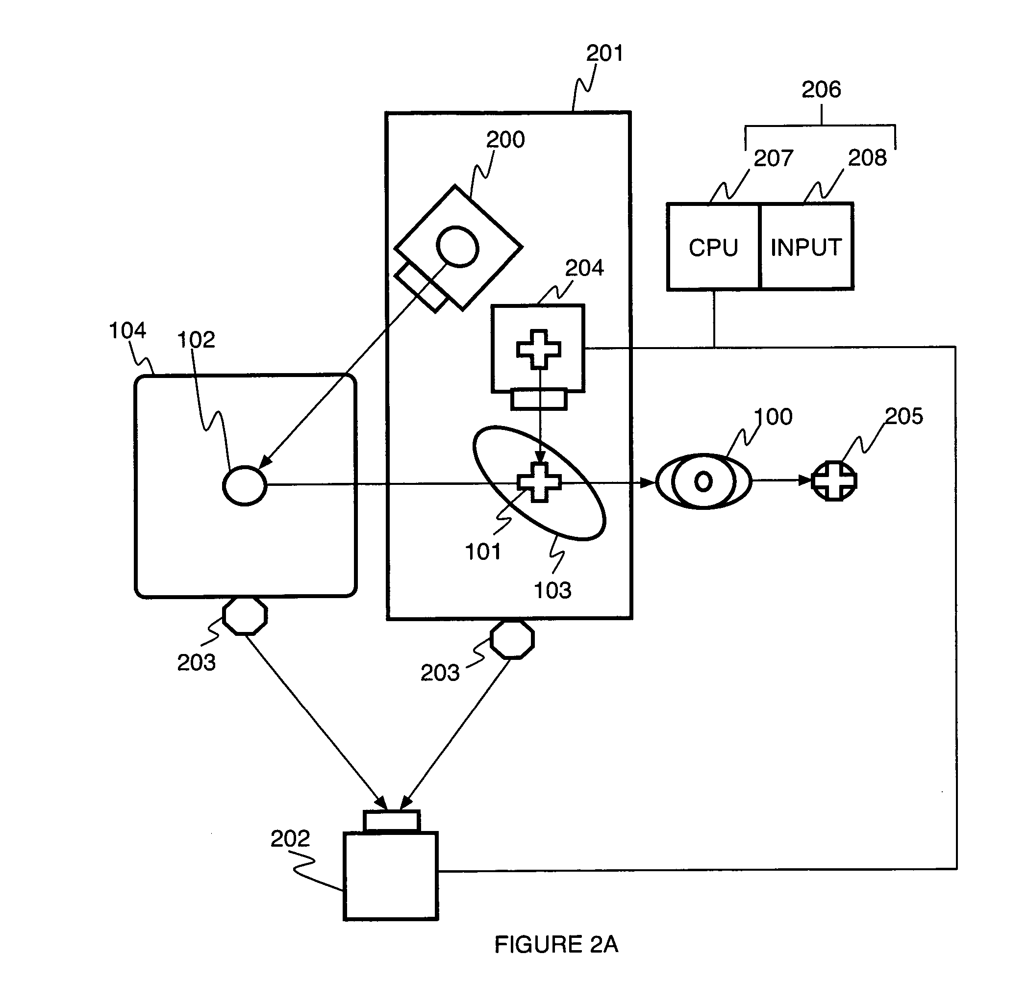
[0030] A system and method for calibration of an optical see-through head-mounted display (HMD) implements a real reference as a light spot originating from an illuminator attached to the HMD. The light spots “jitter along” with the HMD, and the user does not perceive any jitter between these reference markers and virtual markers that are displayed at a fixed location on a semi-transparent screen of the HMD.

[0031] Referring to FIG. 1, to calibrate an optical see-through system, a user 100 aligns a virtual reference 101, displayed as graphics on the HMD's semitransparent screen 103, with a real reference structure 102, observed through the screen 103. The real reference structure 102 is implemented as a projected light point and / or pattern on a calibration screen 104 or other substrate. The real reference 102 and the virtual reference 101 may be, for example, one or more points or shapes.

[0032] It is to be understood that the present invention may be implemented in various forms of...


PUM


Abstract

A method for calibrating real and virtual views includes tracking a calibration screen, wherein a real reference point, generated by a real reference point generator, is projected on the calibration screen, aligning a view of a virtual reference point to a view of the real reference point in a display, wherein the real reference point generator and the display have a fixed relative position, determining a point correspondence between the virtual reference point and the real reference point, and determining one or more parameters for rendering a virtual object in the real scene.

Description

BACKGROUND OF THE INVENTION [0001] 1. Field of the Invention [0002] The present invention relates to augmented reality, and more particularly to a system and method for augmented reality calibration of see-through head-mounted displays. [0003] 2. Discussion of Related Art [0004] Augmented vision, also referred to as augmented reality or augmented reality vision, augments a user's view of the real world with superimposed computer generated graphical information. This information may be include, for example, a text label attached to some object in the scene, or a three-dimensional (3D) model of a patient's brain, derived from an MRI scan, and aligned to the real view of the person's head. [0005] The user may observe the real world directly with his or her eyes, and the additional graphics information is blended in via a semi-transparent display located between the observer and the real scene. Such a display device can, for example, be an optical see-through head mounted display. [0006...

Claims


Application Information

Patent Timeline
Patent Type & Authority Applications(United States)
IPC IPC(8): G09G5/00G02B27/00G02B27/01G06F3/01
CPCG02B27/0101G02B27/0189G02B2027/0138G02B2027/0187G06F3/012
Inventor SAUER, FRANKGENC, YAKUPNAVAB, NASSIR
Owner SIEMENS MEDICAL SOLUTIONS USA INC
Why Eureka
Try Eureka