Display and method for driving same

a technology of display device and display method, applied in static indicating device, non-linear optics, instruments, etc., can solve the problems of slow response of image display, significantly degraded visibility, and reduced visibility, and achieve satisfactory display quality and visibility.

Inactive Publication Date: 2006-07-13
PANASONIC CORP
View PDF5 Cites 14 Cited by
  • Summary
  • Abstract
  • Description
  • Claims
  • Application Information

AI Technical Summary

Benefits of technology

[0011] The present invention has been made to solve the foregoing problems, and an object of the present invention is to provide a particulate material utilizing display device which offers a satisfactory color reproducible range without its visibility being degraded even in a dark environment with poor extraneous light, and a driving method thereof.
[0012] To attain this object, a display device according to the present invention includes a pair of opposite substrates, a group of electrostatically chargeable colored particles present between the pair of substrates, a transparent first electrode, and a second electrode, wherein the group of colored particles is capable of traveling in a manner to or not to shut off light incident on or passing through the first electrode in accordance with voltage applied across the first and second electrodes for displaying an image. Such a construction is capable of obtaining an image which is satisfactory in display quality and visibility.
[0013] This display device has a light source for emitting light. With such a feature, it is possible to obtain an image having satisfactory visibility even in an environment with poor extraneous light.

Problems solved by technology

In use of the aforementioned electrophoretic display device, however, the liquid exhibits high resistance to migration of electrophoretically migratory particles in the liquid phase and, hence, the device involves a problem of slow response in image display.
Such a conventional display construction using particles, however, raises a problem that the device offers satisfactory visibility only in an environment with extraneous light while suffering from lowered visibility in an environment with insufficient extraneous light.
That is, the conventional display construction involves the problem that it suffers from considerably degraded visibility in a dark environment such as nighttime.
However, this configuration raises a problem that the visibility lowers due to environmental light in image display within a satisfactory color reproducible range.
That is, the problem is such that as the color reproducible range is enlarged, an image displayed under a condition with poor environmental light becomes darker.
This method has difficulties in differently coloring and distributing the particles for respective of R, G and B pixels.
For this reason, the image display device has problems that higher driving voltage is needed and that the resolution of an image displayed is lowered.
If the layer of white particles is made thinner to avoid these problems, another problem arises that the white color becomes dark and, particularly in a dark room such as an indoor place during nighttime, the white display becomes difficult to view.
In color display, use of the configuration employing color filters or the configuration using differently colored particles is possible as described above, these configurations suffer from lowered reflectance and hence has a difficulty in reproduction of bright colors.

Method used


Image

  • Display and method for driving same
  • Display and method for driving same
  • Display and method for driving same

Examples


embodiment 1

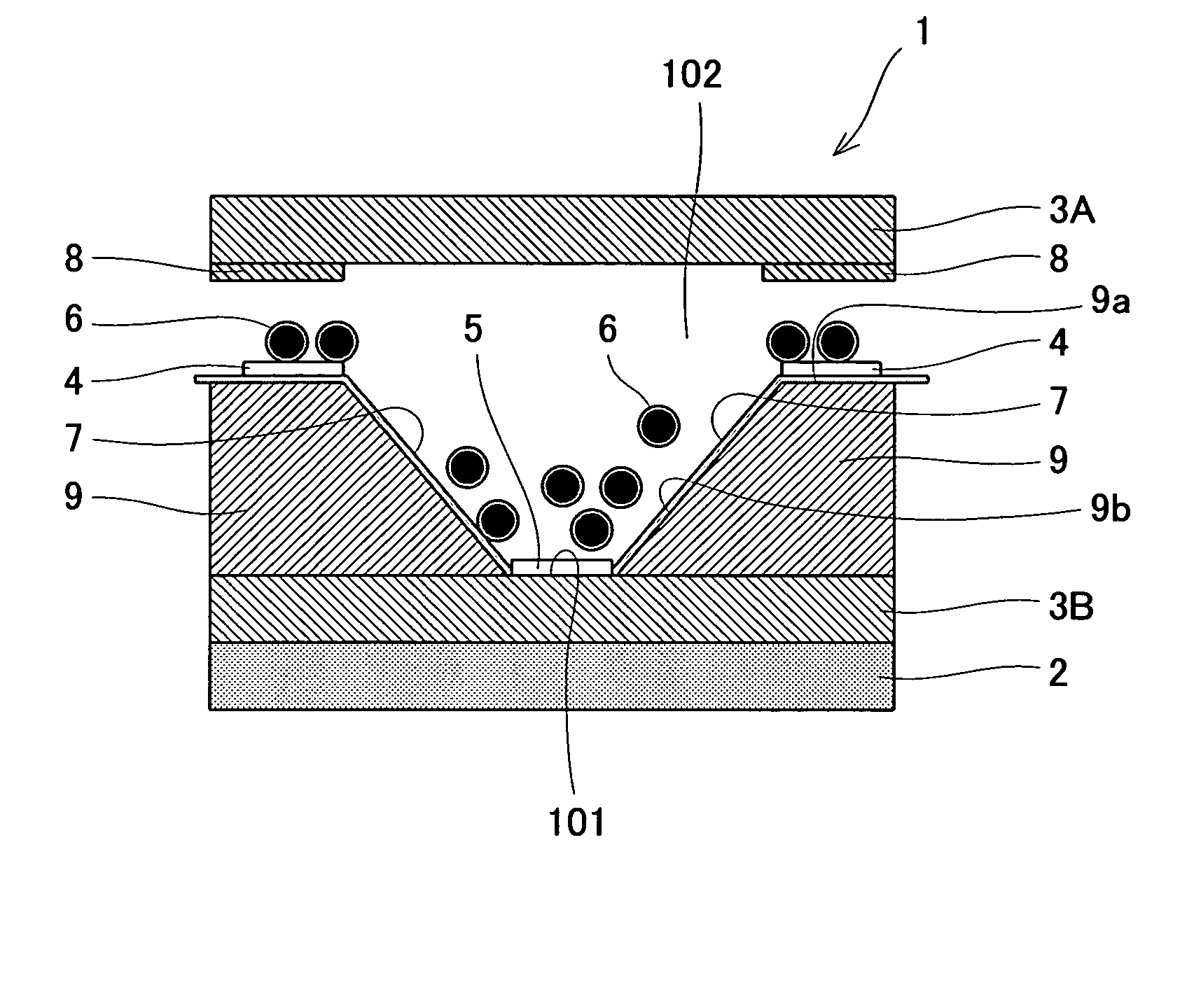
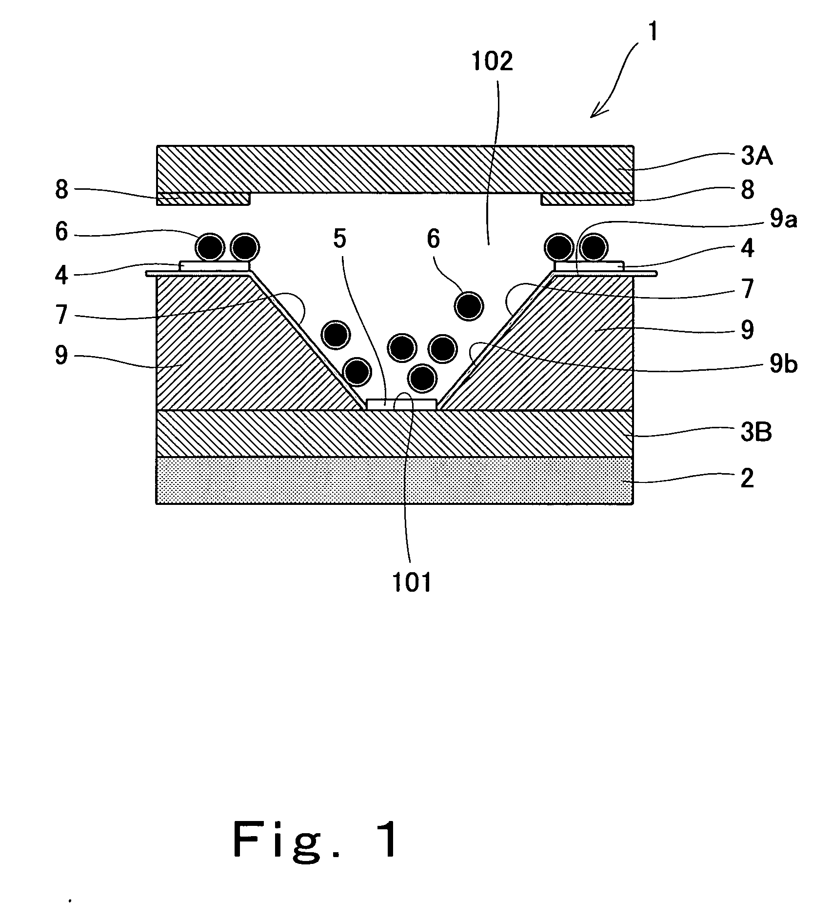
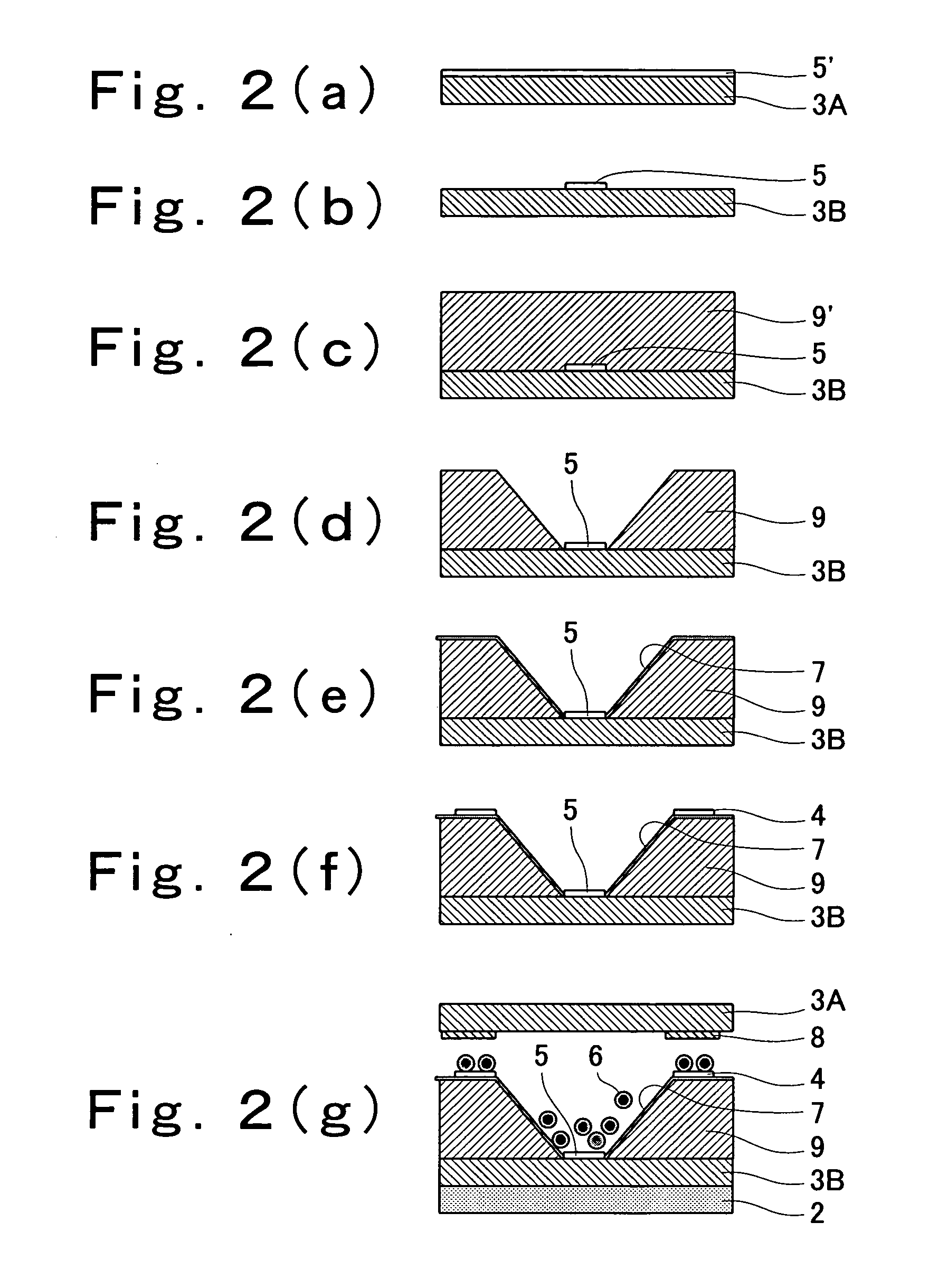
[0052]FIG. 1 is a sectional view schematically showing the construction of a display device according to embodiment 1 of the present invention; and FIGS. 2(a) to 2(g) are sectional views schematically illustrating process steps included in a fabrication method of the display device according to embodiment 1 of the present invention.

[0053] The display device according to the present embodiment has one pixel. A display device having plural pixels will be described later in the description of embodiment 4.

[0054] As shown in FIG. 1, display device 1 according to the present embodiment includes a transparent front substrate 3A and a transparent rear substrate 3B, which are positioned to face each other. The transparent substrates 3A and 3B each comprise a transparent resin substrate for example. The transparent rear substrate 3B has an inwardly oriented surface formed with a pair of uneven members 9,9. In this embodiment, each uneven member 9 is formed to have a trapezoidal section wit...

embodiment 2

[0066] Monochromatic display (black and white display for example) has been described in Embodiment 1. In Embodiment 2, description is made of the case where color display is realized by the use of the display device according to embodiment 1.

[0067]FIG. 5 is a sectional view schematically showing the construction of a display device according to embodiment 2 of the present invention.

[0068] As shown in FIG. 5, the display device 1 according to the present embodiment has backlight 2 operative to emit white light as a light source, transparent front substrate 3A and transparent rear substrate 3B, light blocking electrode 4, transparent electrode 5, electrostatically chargeable fine particles 6, reflective film 7, light blocking members 8, and uneven members 9. On the surface of the transparent electrode 5 is provided a red color filter 10 having a predetermined thickness and substantially the same shape as the transparent electrode 5. Other features are in common with the correspondi...

embodiment 3

[0081]FIG. 8 is a block diagram showing the configuration of a display device according to embodiment 3 of the present invention.

[0082] As shown in FIG. 8, the display device 100 according to embodiment 3 includes a display section 28 having sub-pixels 29 arranged in matrix. Each of the sub-pixels 29 constituting the display section 28 has first and second electrodes, as will be described later. The first and second electrodes are connected to first and second electrode drivers 26 and 27, respectively. That is, each sub-pixel 29 is driven by the first and second electrode drivers 26 and 27. The operations of the respective first and second electrode drivers 26 and 27 are controlled by a control section 25 in accordance with video signals inputted to the control section 25. Thus, the display device 100 according to this embodiment comprises the control section 25, first and second electrode drivers 26 and 27, and display section 28 comprising the sub-pixels 29.

[0083] The following ...


PUM

PropertyMeasurementUnit
response timeaaaaaaaaaa
particle diameteraaaaaaaaaa
thicknessaaaaaaaaaa

Abstract

A display device (1) according to this invention includes a pair of opposite substrates (3A) and (3B), a group of electrostatically chargeable colored particles (6) present between the pair of substrates, a transparent first electrode (4), and a second electrode (5), wherein the group of colored particles is capable of traveling in a manner to or not to shut off light incident on or passing through the first electrode in accordance with voltage applied across the first and second electrodes for displaying an image.

Description

TECHNICAL FIELD [0001] The present invention relates to a display device for image display and a driving method thereof and, more particularly, to a display device configured to cause particulate material to travel between electrodes thereby to display images and a driving method thereof. BACKGROUND ART [0002] In these years, particulate material utilizing displays configured to cause fine particles to travel between electrodes thereby to display images have been widely used as image display devices to be incorporated in image equipment such as information processing equipment or image processing equipment. [0003] Conventional particulate material utilizing displays (electronic paper or the like for example) rely upon such image display techniques as rotation of colored particles and electrophoresis. These image display techniques realize image display by utilizing the difference in extraneous light reflection between a colored particle and an organic solvent or the like around the ...

Claims


Application Information

Patent Timeline
Patent Type & Authority Applications(United States)
IPC IPC(8): G09G3/34G02F1/1677
CPCG02F1/167G02F1/1677G02F1/1685G02F1/1681G02F2203/055G02F2201/34
Inventor NISHIYAMA, SEIJIWAKITA, NAOHIDE
Owner PANASONIC CORP
Why Eureka
Try Eureka