Casing structure of mouse
- Summary
- Abstract
- Description
- Claims
- Application Information
AI Technical Summary
Benefits of technology
Problems solved by technology
Method used
Image

Examples
first embodiment
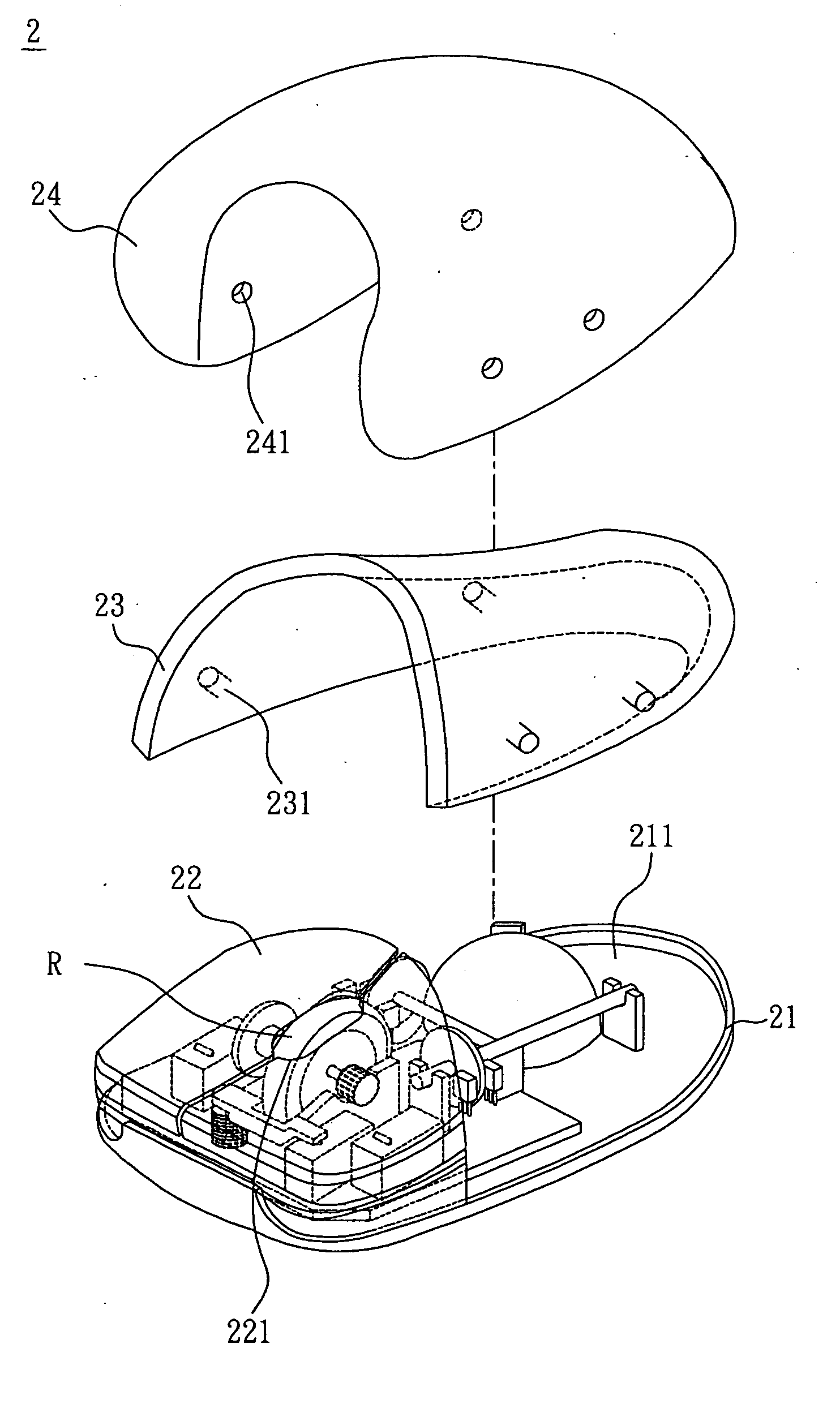
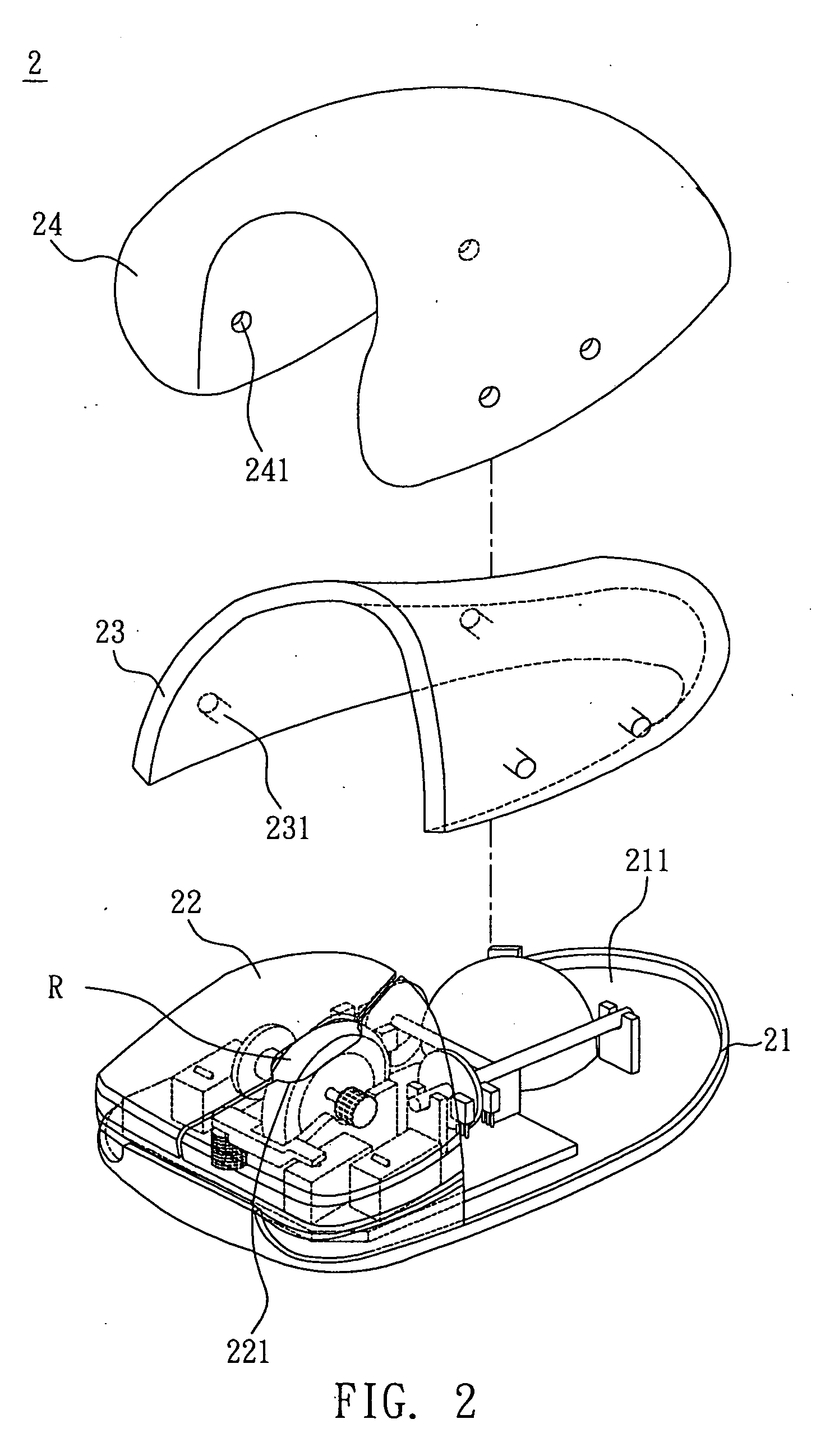
[0020] Please refer to FIGS. 2 and 3, a casing structure of a mouse is disclosed.
[0021] As shown in FIG. 2, the casing structure of the mouse 2 includes a base 21, an upper cover 23, and a soft pad 24.
[0022] The upper cover 23 is disposed on the base 21 to form an accommodating space 211. The accommodating space 211 is used to hold the internal mechanical structure of the mouse, such as the track ball, grating, and circuit board. In this embodiment, the upper cover 23 may be made of plastic. The supporting force provided by the upper cover 23 supports the soft pad 24.
[0023] In the current embodiment, the casing structure of the mouse 2 further includes a button member 22 installed on the base 21 and matching with the upper cover 23. In particular, the base 21 and the button member 22 can be integrally formed through an ejection process. The button member 22 may have an opening 221 for exposing the roller R of the mouse.
[0024] Please refer to FIG. 3 for a schematic view of the bas...
second embodiment
[0028] Please refer to FIG. 4 for a schematic view of a casing structure of a mouse. It is seen from the drawing that the casing structure of the mouse 3 with micro memory includes a base 31, an upper cover 33, and a soft pad 34.
[0029] In this embodiment, the casing structure of the mouse 3 may further include a button member 32 disposed on the base 31 and matching with the upper cover 33. Since the base 31, the button member 32, and the upper cover 33 are the same as the base 21, the button member 22, and the upper cover 23 in the first embodiment, we do not repeat herein.
[0030] In FIG. 4, the soft pad 34 is a soft bag filled with a fluid. In the current embodiment, the material of the soft pad 34 may be thermo-forming plastic (e.g. polyurethane) formed by a stamping or ejection process. The fluid filled inside the soft pad 34 may be a gel (e.g. silicon gel) or a liquid (e.g. water). Moreover, the soft pad 34 may have a hard bottom 342, which sustains a firm combination with the u...
third embodiment
[0032]FIG. 5 shows a schematic view of a casing of a mouse 3. In this embodiment, the casing structure further includes a limiting member 35 mounted around the upper cover 33. It touches against and helps positioning the soft pad 34. The limiting member 35 can be a plastic frame.
[0033] In conclusion, the disclosed casing structure of mouse has a soft pad. In comparison with the prior art, the invention allows a full contact between the user's palm and the mouse casing. This can prevent hand muscles from injuries due to incomplete contact. Therefore, the disclosed mouse is more ergonomic and comfortable. Furthermore, the soft pad provides the user a better touch feeling; and the consumers are thus more willing to purchase. Besides, the manufacturers do not need to separately fabricate casings for left- and right-handed users. Using the soft pad provided on the upper cover, the disclosed mouse can be conveniently used by any person. This greatly reduces the production cost.
PUM
 Abstract
Description
Claims
Application Information