

Vibration measurement device and vibration measurement method
a technology of vibration measurement and measurement device, which is applied in the direction of measurement device, speed/acceleration/shock measurement, instruments, etc., can solve the problems of narrow frequency band that can be measured, wide bandwidth of sensor type, and low sensitivity
- Summary
- Abstract
- Description
- Claims
- Application Information
AI Technical Summary
Benefits of technology
Problems solved by technology
Method used
Image

Examples
example 1
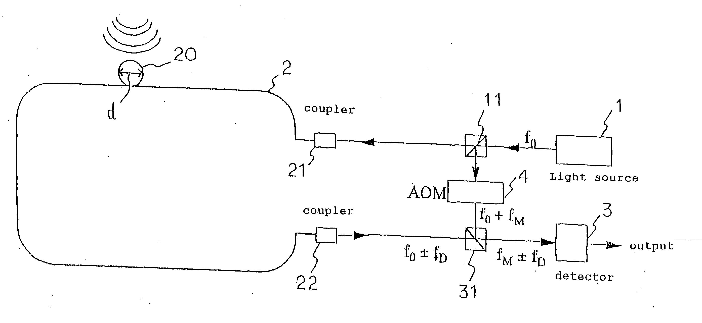
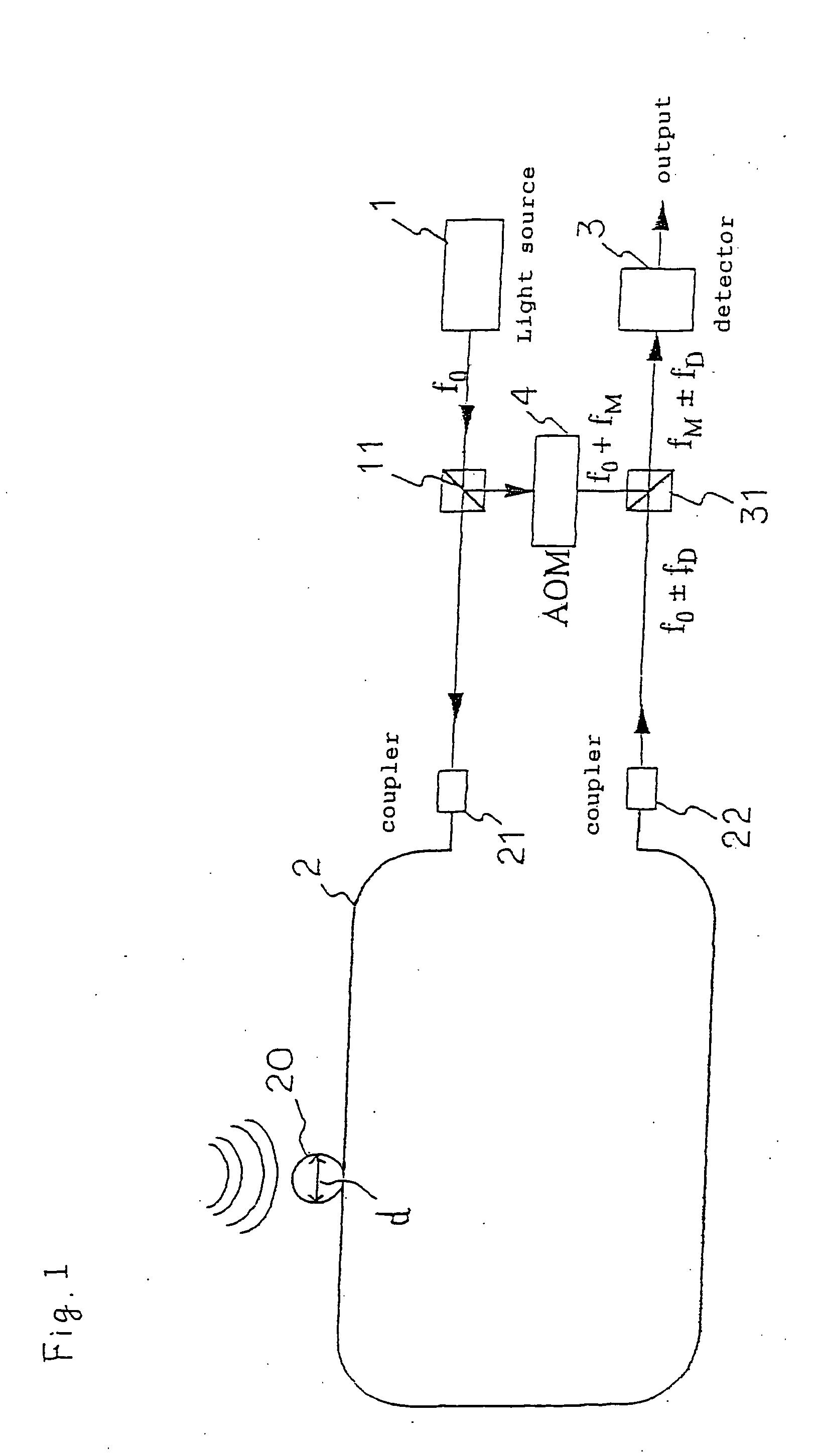
[0084] The whole of a curved section 20 is attached onto a plate (specifically, reinforced plastic) using adhesive tape. Fiber 2 other than the curved section 20 is not attached to the plate. At this time, the curved section 20 is formed by coiling a single turn. The circumference of the curved section 20 is 62 mm. A piezoelectric element is attached on the same plate, as a vibration source. This piezoelectric element therefore applies vibration to the plate according to an applied a.c. voltage. The distance between the curved section 20 and the piezoelectric element is made 50 mm. Referring to FIG. 1, the position of the piezoelectric element is directly above the curved section 20.
[0085] In this state, the piezoelectric element is made to vibrate. A vibration waveform of the piezoelectric element is shown in FIG. 3(a), while a frequency spectrum obtained through Fourier analysis of this vibration is shown in FIG. 3(b). Also, frequency variation of output light at this time is sho...
example 2
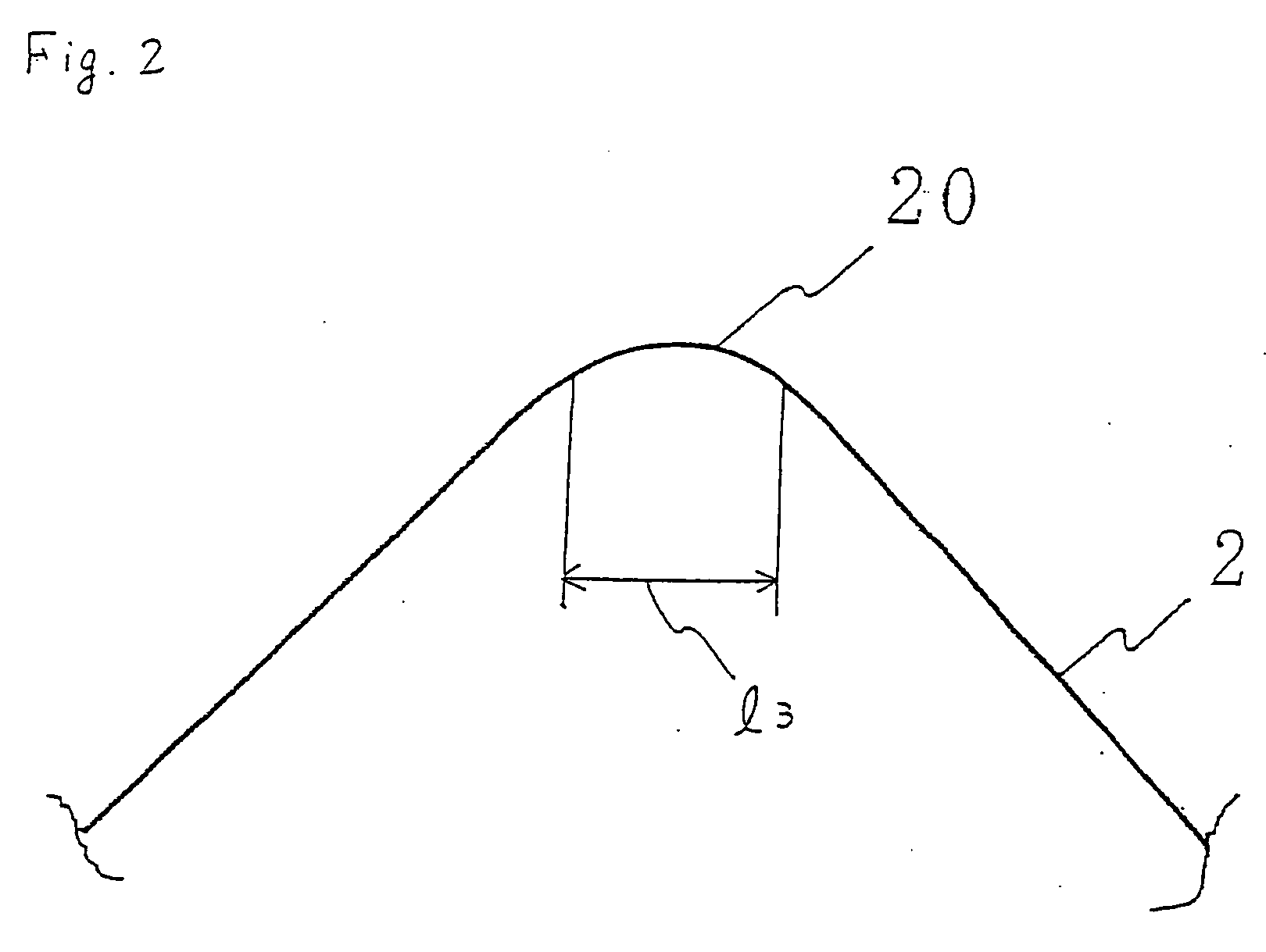
[0089] With example 2, the curved section 20 was formed having one side (center of curvature side) open, the same as in the example of FIG. 2. Other conditions were the same as for example 1.
[0090] Under these conditions, the piezoelectric element was made to vibrate. The position of the piezoelectric element was varied 30° at a time. Amount of frequency variation in response to angle is shown in the graph of FIG. 5(a) as a voltage value. FIG. 5(b) is a graph representing this amount of variation as a logarithm. Here, the method of acquiring an angle is shown in FIG. 5(c). With this example, rotation in the θ direction in the drawing (that is, in an anti-clockwise direction) is made positive. A radius of curvature at a tip of the curved section 20 is about 5 mm, and an overall bending angle is about 90°.
[0091] From these results, it will be understood that in the case of opening one side of the curved section 20, there is directivity, meaning that sensitivity to vibration from a c...
example 4
[0106] A steel cylindrical member was used as the object to be measured 5, and vibration measurement performed. First of all, the device structure will be described based on FIG. 14. The length of the object to be measured l1 was 4 m, and the diameter was 15 mm. As mentioned in the second embodiment described above, the optical fiber 2 was looped around the object to be measured 5. The location for the loop was made a distance l2 of about 50 cm from one end (the left end in the drawing) of the object to be measured 5. A curved section 20 was made by looping the optical fiber 2. Similarly to FIG. 1, suitable components such as an input section 1, detection section 3 and AOM 4 are connected to the optical fiber 2. In this example, a band pass filter (not shown) for extracting a specified frequency band from among vibrations detected by the detection section 3 is also connected. This filter can be formed as an analog filter or a digital filter.
[0107] An ultrasonic oscillator 7 is atta...
PUM
 Abstract
Description
Claims
Application Information