End lighted endotracheal tube

a technology of endotracheal tubes and endotracheal tubes, which is applied in the field of endotracheal tubes, can solve the problems of bulky external light sources, lack of training and skill, and difficulty in insertion

Inactive Publication Date: 2006-07-20
JOHNSON DOUGLAS R +1
View PDF12 Cites 30 Cited by
  • Summary
  • Abstract
  • Description
  • Claims
  • Application Information

AI Technical Summary

Benefits of technology

[0008] The present invention provides apparatus, systems and methods in which an endotracheal ...

Problems solved by technology

Despite the prevalence of such tubes, however, their insertion remains a matter of training and skill.
That concept accommodates use of a very bright light source, but creates its own problems.
Among other things an external light source is bulky and generally requires a plug in type power source rather than merely a bat...

Method used


Image

  • End lighted endotracheal tube
  • End lighted endotracheal tube

Examples


Embodiment Construction

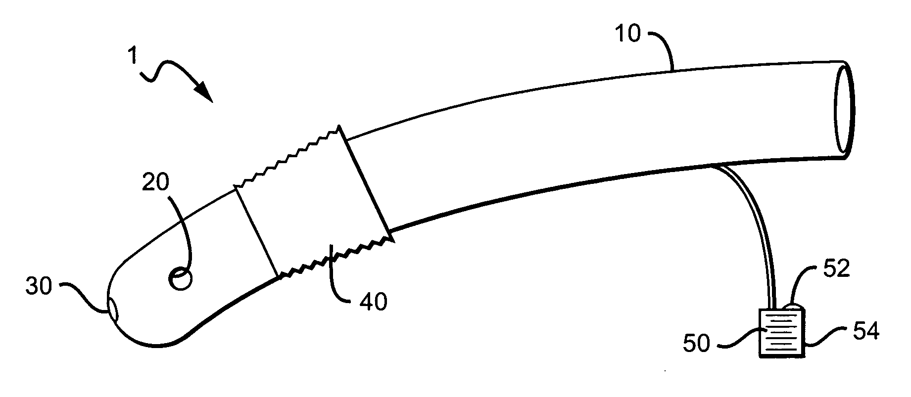
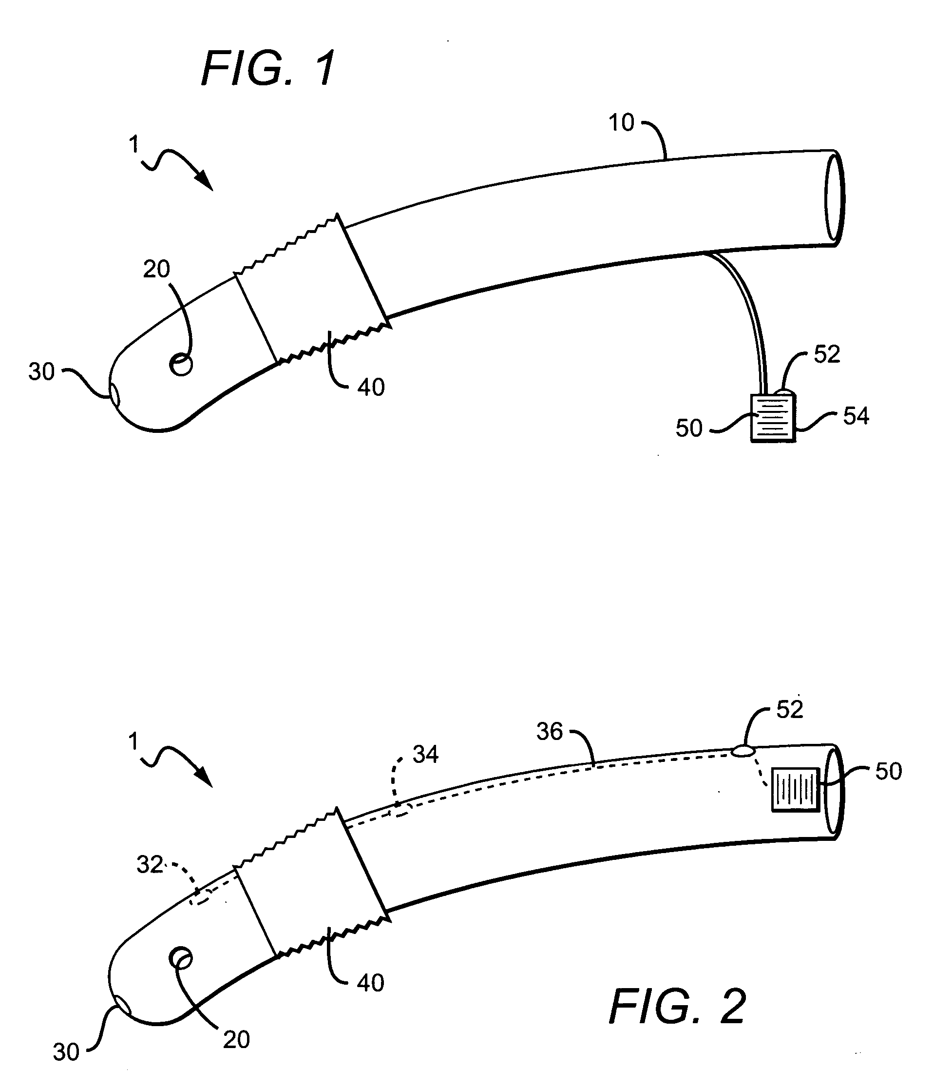
[0012] In FIG. 1 an endotracheal tube 1 generally has a tube body 10, an air hole 20, a light source 30, a cuff 40, and a power supply 50.

[0013] Tube body 10 can be manufactured from any suitable material, and can have any suitable dimensions. Indeed the present inventor contemplates use of all materials and dimensions previously used to manufacture endotracheal tube bodies, as well as their replacements. Preference, however, is more restricted. Any material overlying the light source 30 should be sufficiently transparent or translucent to pass a desirable intensity of visible light.

[0014] Air hole 20 and cuff 40 are similarly contemplated to conform to any suitable materials, positions, dimensions, and so forth. Pediatric devices, for example, would have significantly smaller dimensions than devices intended for adults.

[0015] In FIG. 1, the light source 30 is positioned near, but not at, the end of tube 1. The term “near” is defined herein as within 2 cm, and more preferably wit...


PUM


Abstract

An endotracheal tube has a light-emitting diode or other low temperature, built-in light source forward of the cuff.

Description

FIELD OF INVNENTION [0001] The field of the invention is medical devices, and more particularly endotracheal tubes. BACKGROUND [0002] Endotracheal tubes are commonplace in the medical field, both in medical facilities and in the field. Despite the prevalence of such tubes, however, their insertion remains a matter of training and skill. [0003] The advent of lighted endotracheal tubes significantly improved the success rate of intubation. Lighted stylet guided intubation has been found to be particularly useful for difficult situations, such as anterior larynx scarring and bloody airway, and is in any event generally less traumatic for the patient. Among other things, lighted stylet intubation reduces manipulation of the head and neck, and the need for excessive opening of the mouth. There are numerous such devices on the market, including Trachlite® (Rusch), Trachlight® (Laerdal), Surch-lite® (Aaron Medical), and Lightwand”®. [0004] Endotracheal tubes can also be lighted without a r...

Claims


Application Information

Patent Timeline
IPC IPC(8): A62B9/06A61M16/00
CPCA61M16/0411A61M16/04
Inventor JOHNSON, DOUGLAS R.GARTH, GEOFFREY
Owner JOHNSON DOUGLAS R
Why Eureka
Try Eureka