
Image output system and method for notifying information

a technology of image data and output system, applied in the direction of digital output to print unit, visual presentation, instruments, etc., can solve the problems of not being able to connect to the internet for all image data supplying devices, difficult for an operator to understand the contents of code data, and inability to cope with new code data, etc., to achieve easy and appropriate notification.

Inactive Publication Date: 2006-07-20
SEIKO EPSON CORP
View PDF9 Cites 3 Cited by
  • Summary
  • Abstract
  • Description
  • Claims
  • Application Information

AI Technical Summary

Benefits of technology

The invention provides a system for easily notifying an operator of an image output device about the operation of the device. The system includes an image output device and an image data supplier device connected through an image output device. The image output device outputs information in a form that is easy for the operator to understand, such as text, image, or sound data. The information is received by the image data supplier device and directly reproduced for the user. This simplifies the system and makes it easier for the operator to provide appropriate information to the user. The system can also adapt the information based on the user's needs and the device's capabilities. Overall, the invention provides a technique for providing relevant and easily understandable information to the operator of an image output device.

Problems solved by technology

Further, since it is difficult for an operator to understand the contents of code data, a technique is proposed whereby an image output device supplies code data to an image data supplying device, and the image data supplying device translates the code data and prepares a display form (as disclosed, for example, in Japanese Patent Publication No. 2002-236783A).
Therefore, by using a method whereby code data are simply standardized in advance, these new code data can not be coped with.
However, not all image data supplying devices can be connected to the Internet, nor can they read required data from recording media.
Moreover, these problems are not limited to a case wherein the operation state of an image output device is displayed, and could also occur in a case wherein specific information, transmitted to an operator, includes the operating method employed by the image output device.

Method used


Image

  • Image output system and method for notifying information
  • Image output system and method for notifying information
  • Image output system and method for notifying information

Examples


Embodiment Construction

[0074] Embodiments of the invention will be described below in detail with reference to the accompanying drawings.

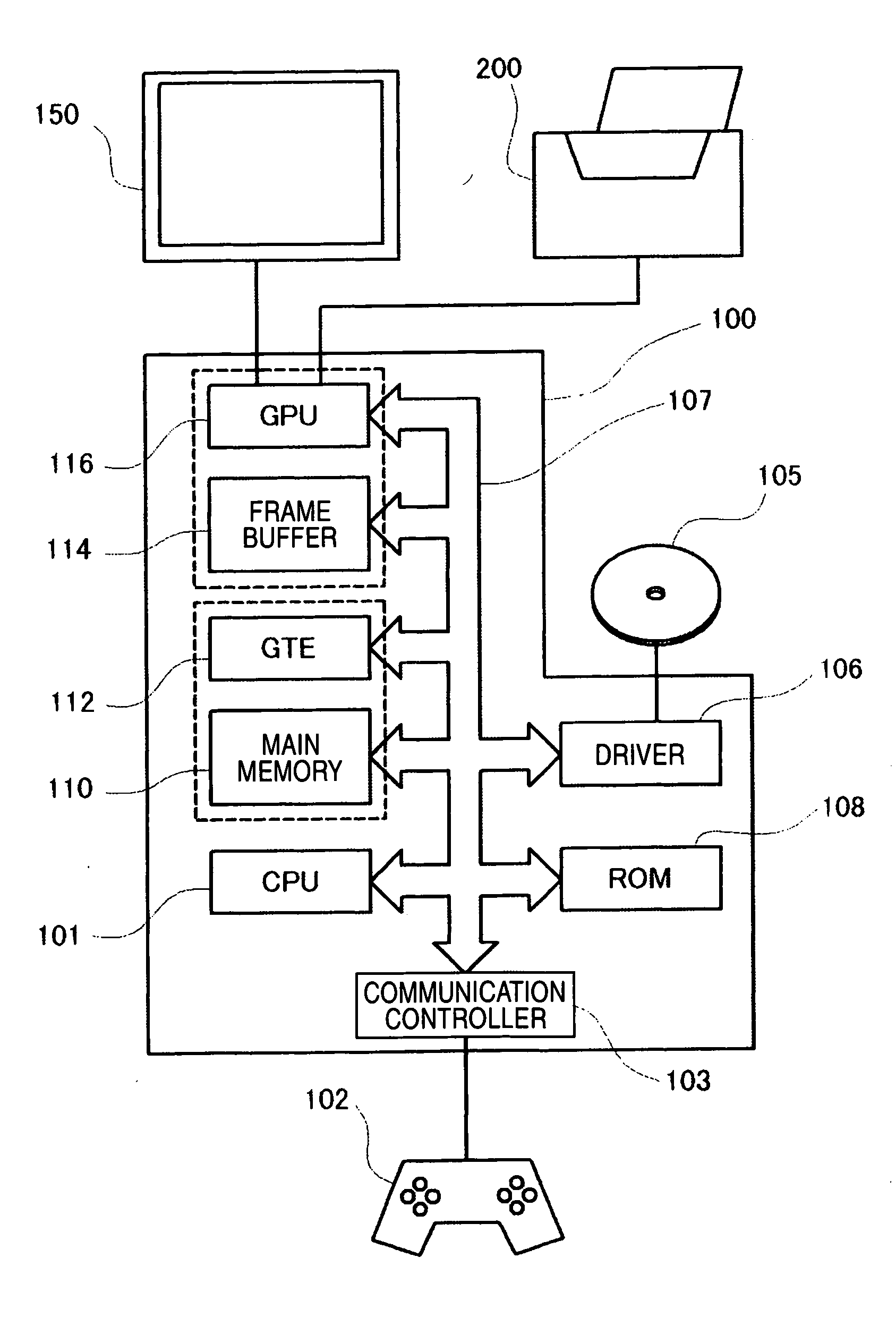
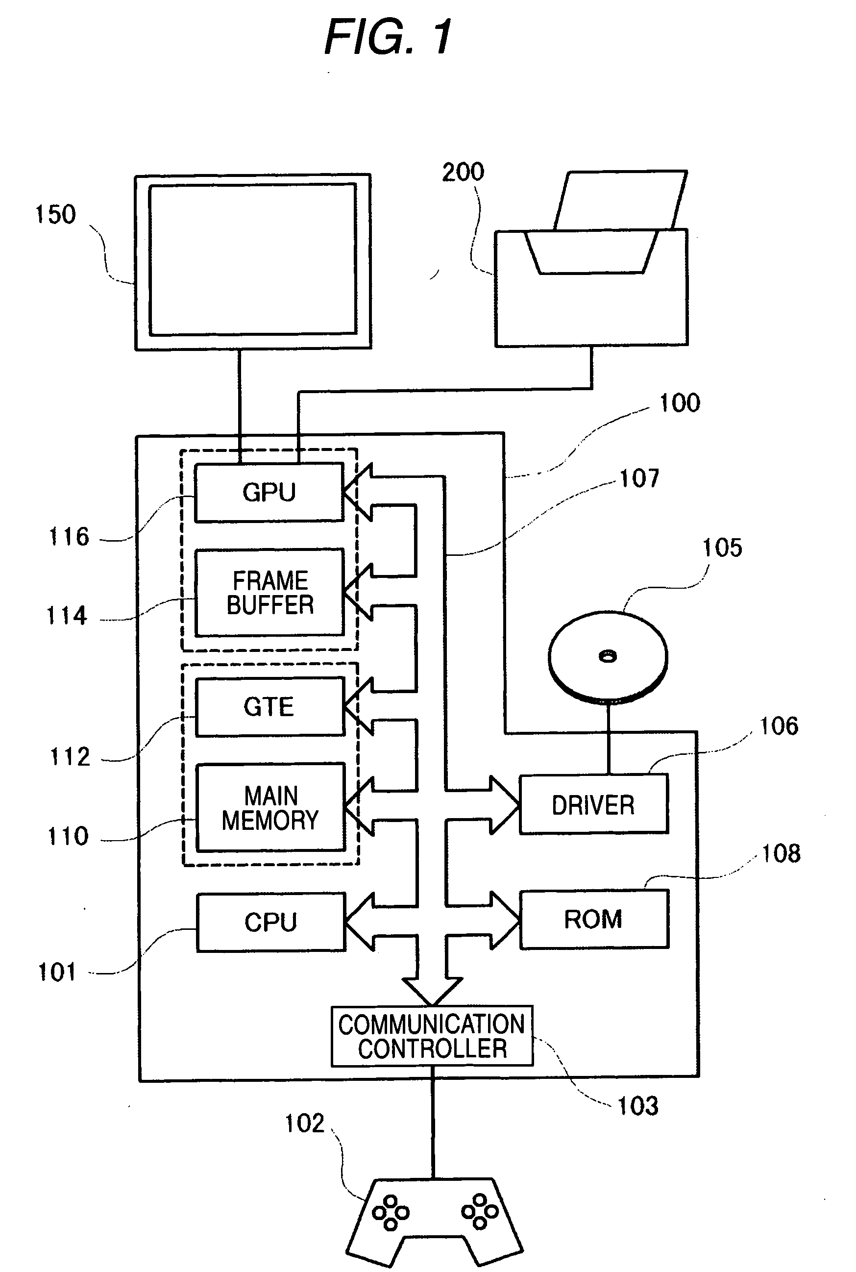
[0075]FIG. 1 is a block diagram showing an image output system constituted by a game machine 100 and a color printer 200 according to one embodiment of the invention. The game machine 100 is constituted by connecting a main memory 110, a coordinates transformer (hereinafter, the GTE: Geometry Transfer Engine) 112, a frame buffer 114, an image processor (hereinafter, the GPU: Graphic Processing Unit) 116, a the ROM 108, a driver 106, a communication controller 103 and the like to be able to exchange data from each other by way of a bus centering on the CPU 101. Further, the game machine 100 is connected with a controller 102 or the like for operating the game machine 100. Further, the game machine 100 is also connected with the color printer 200 to be able to output a screen in the midst of a game by the color printer 200.

[0076] The CPU 101 is a central processing unit ...


PUM


Abstract

An image output device is operable to output an image based on an image data. An image data supplying device is operable to supply the image data to the image output device. An information output device is provided in the image output device and operable to output information to the image data supplying device as a first data form, the information adapted to be presented to a user and including at least one of text data, image data and sound data. An information reproducing device is provided in the image data supplying device and configured to reproduce the information directly based on the first data form.

Description

BACKGROUND OF THE INVENTION [0001] The present invention relates to a technique for notifying, to an operator of an image output device, information relevant to the operation of the image output device. [0002] For recent image output devices, such as so-called ink jet printers and laser printers, remarkable improvements have been made in various aspects, such as image displaying speed and quality. Therefore, image output devices can be employed for any image types used for artificial images, such as letters and figures, and natural images, such as photographs. Further, accompanying these improvements, various types of apparatuses, such as computers, digital cameras and mobile phones, can be connected to image output devices, and can be used as image data supplying devices to supply image data to the image output devices. [0003] When the operation state of an image output device, such as “data-reception”, “image output”, “no ink” or “no paper”, is to displayed, generally, code data c...

Claims


Application Information

Patent Timeline
Patent Type & Authority Applications(United States)
IPC IPC(8): G06F3/12
CPCG06K15/00G06K15/007
Inventor OTANI, TSUTOMU
Owner SEIKO EPSON CORP
Learn More