Monitoring camera system

a camera system and monitoring technology, applied in the field of monitoring camera systems, can solve the problems of complex work, sensor operation that cannot meet the user's expectations, and user's complicated work, etc., and achieve the effect of simple setting operation, easy viewing display, and easy setting and updating of sensor setting information

Active Publication Date: 2018-08-07
PANASONIC INTELLECTUAL PROPERTY CORP OF AMERICA
View PDF26 Cites 0 Cited by
  • Summary
  • Abstract
  • Description
  • Claims
  • Application Information

AI Technical Summary

Benefits of technology

[0008]An object of the present invention is to provide a communication system that simplifies an operation of setting and updating sensor setting information of at least one installed sensor or setting information of a controlled unit so as to solve the conventional problems described above.
[0010]Accordingly, the monitoring camera system of the present invention can simplify an operation of setting and updating the sensor setting information of the respective sensors installed in each group through an easily viewable display and input unit of the portable terminal carried by the user, and easily set and update the sensor setting information.

Problems solved by technology

Therefore, the setting value may not meet actual individual circumstances of the user, or the sensor may not operate as expected by the user.
Further, when the user changes the setting value (for example, sensitivity, and the threshold value) of the sensor into an appropriate setting value while actually confirming that the sensor detects the target (for example, an intruder), work of the user performing setting and changing while coming and going from and to an installation place of the sensor and an installation place of a receiver (for example, master device) that receives information (for example, information indicating abnormality) detected by the sensor occurs, and thus, there are problems in that complicated work is required for the user, and convenience for the user deteriorates.

Method used


Image

  • Monitoring camera system
  • Monitoring camera system
  • Monitoring camera system

Examples


first embodiment

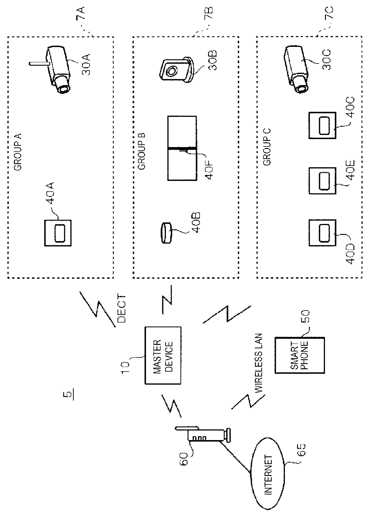
[0039]FIG. 1 is a schematic diagram illustrating a configuration of monitoring camera system 5 of a first embodiment. Monitoring camera system 5 illustrated in FIG. 1 is configured to include master device 10 installed indoors and outdoors, three cameras 30 (specifically, monitoring cameras 30A and 30C, and indoor camera 30B), various sensors 40 (specifically, human sensor 40A, smoke sensor 40B, human sensors 40C, 40D, and 40E, and opening and closing sensor 40F), smartphone 50, and wireless router 60. A configuration of monitoring camera system 5 illustrated in FIG. 1 is an example, and can be changed in various aspects according to a use.

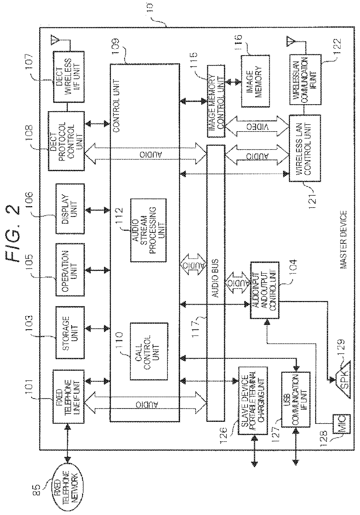
[0040]Master device (gateway) 10 is a control device that controls an entire operation of monitoring camera system 5, and is connected to be able to communicate with a slave device (not illustrated), the cameras, the sensors, or the like using a communication scheme of DECT (Digital Enhanced Cordless Telecommunications). Further, master device 10 ...

second embodiment

[0093]The case in which sensor setting values of one or a plurality of sensors 40 belonging to the same group are individually set has been described in the first embodiment described above.

[0094]A case in which threshold values of one or a plurality of sensors 40 associated with one camera 30 are collectively set will be described in a second embodiment.

[0095]Further, in the first embodiment, the zone and the camera correspond on a one to one basis by setting the imaging range of the camera as the zone, whereas in the second embodiment, a previously set region may be set as a zone, and a plurality of cameras may be installed in this region, or no camera may be installed.

[0096]In the second embodiment, one camera is added to zone C and two monitoring cameras 30C and 30D (camera CC and camera DD) are installed, unlike in the first embodiment. Further, in the second embodiment, when the threshold values of the sensors are collectively set for each zone, only the sensors associated wit...

third embodiment

[0109]In the first embodiment described above, the group to which one or a plurality of sensors belong is set in advance, whereas in a third embodiment, a case in which a user sets a group to which one or a plurality of sensors belong from an image captured by a camera will be described.

[0110]A monitoring camera system of the third embodiment has substantially the same configuration as that of the first embodiment. The same components as those in the first embodiment are denoted with the same reference numerals, and description thereof will be omitted.

[0111]FIG. 15 is a sequence diagram illustrating a flow of a sensor setting operation in monitoring camera system 5 of the third embodiment. When the user taps the icon for a sensor camera setting function displayed on touch panel 503 of smartphone 50, similarly to the second embodiment described above (S41), smartphone 50 starts up an application for a sensor camera setting function and transmits a start-up signal to master device 10 ...


PUM


Abstract

A master device transmits received image data to a mobile phone terminal and includes a storage unit that stores sensor setting information including at least sensitivity or a threshold value of a sensor, the mobile phone terminal includes a display and input unit, displays the image data transmitted from the master device on the display and input unit, requests the master device to provide the sensor setting information when receiving a predetermined operation, displays the sensor setting information transmitted from the master device on the display and input unit, and transmits the changed sensor setting information to the master device when receiving an operation of changing the sensor setting information, and the master device updates the sensor setting information stored in the storage unit using the sensor setting information after changing transmitted from the mobile phone terminal.

Description

BACKGROUND OF THE INVENTION[0001]1. Field of the Invention[0002]The present invention relates to a monitoring camera system that performs transmission and reception of information or data to and from a monitoring camera and a sensor.[0003]2. Description of the Related Art[0004]A monitoring camera system that monitors an intruder entering a site of a house is conventionally known as an example of a communication system that performs transmission or reception of information or data with a sensor. For example, a monitoring camera system shown in Japanese Patent Unexamined Publication No. 2000-99862 includes a home server capable of recording a video or an audio, an infrared sensor, a video camera, and a microphone. When the infrared sensor detects an intruder, the home server records a video regarding the intruder and an audio regarding the intruder using the video camera and the microphone.[0005]However, in Patent Unexamined Publication No. 2000-99862 described above, a setting value ...

Claims


Application Information

Patent Timeline
Patent Type & Authority Patents(United States)
IPC IPC(8): H04N7/18H04N5/44G08B25/08
CPCH04N5/44H04N7/185G08B25/08
Inventor SATO, KEIZOKAWAMURA, MITSURU
Owner PANASONIC INTELLECTUAL PROPERTY CORP OF AMERICA
Why Eureka
Try Eureka