Hanger for rope or the like

a hook and hook technology, applied in the field of rope hooks, can solve the problem that the situation cannot be realized without intentional support, and achieve the effect of convenient operation and good at its safety

Inactive Publication Date: 2006-07-27
NIICHI +1
View PDF4 Cites 32 Cited by
  • Summary
  • Abstract
  • Description
  • Claims
  • Application Information

AI Technical Summary

Benefits of technology

[0012] The present invention is provided through taking the above-mentioned disadvantages of the rope hook of the prior art into consideration. Accordingly the object of the present invention is to provide a remarkably exce

Problems solved by technology

Such situation cannot be realized

Method used


Image

  • Hanger for rope or the like
  • Hanger for rope or the like
  • Hanger for rope or the like

Examples


first embodiment

i) The First Embodiment

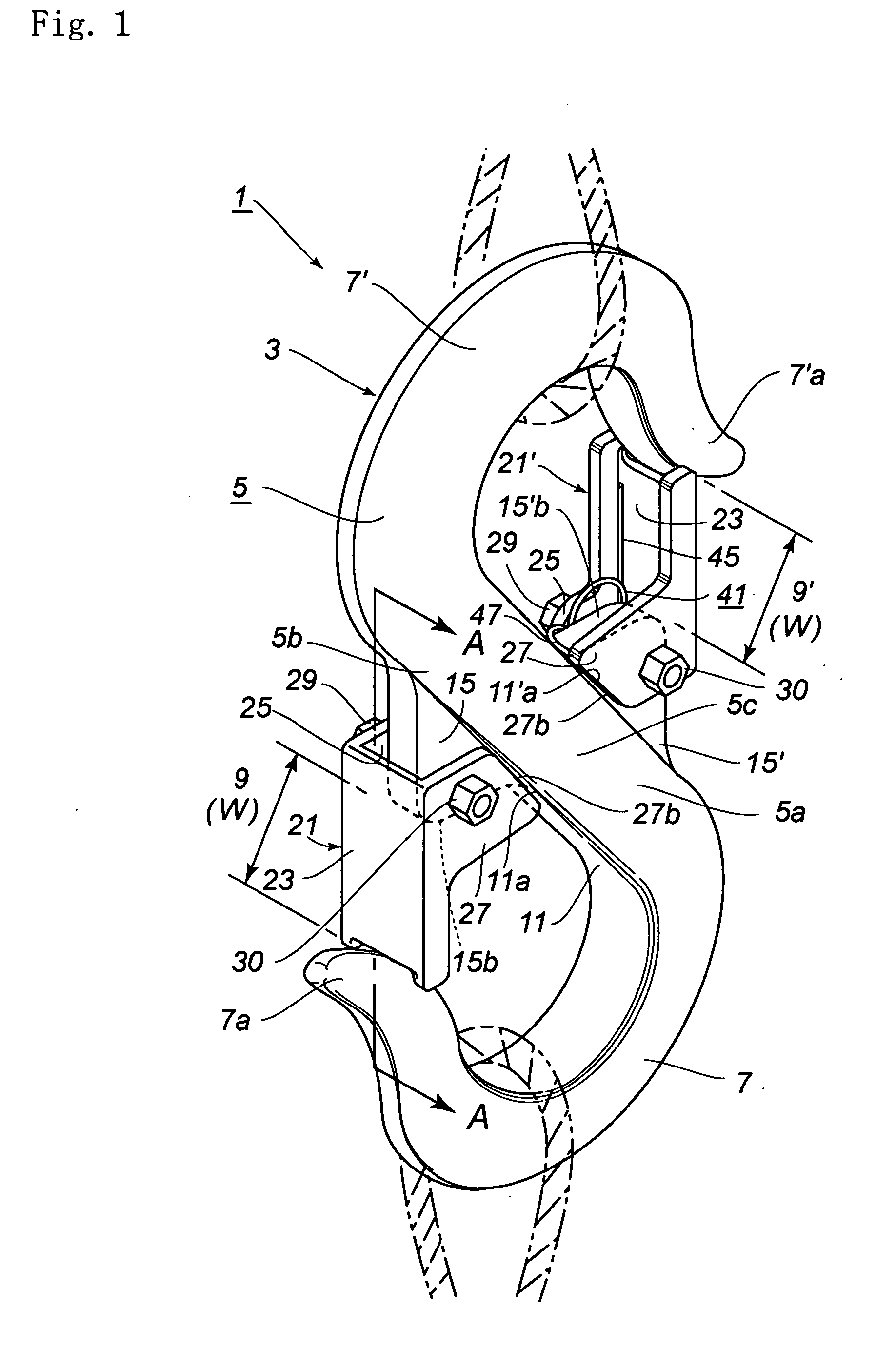
[0050] [A. Construction (see FIGS. 1-5)]In the following detailed description of the first embodiment, reference is made to FIG. 1 in which the direction to the left and lower side of FIG. 1 is that to the front side of the rope hook, the direction to the upper side of the drawing is that to the upper side of the rope hook, and the direction to the left and upper side of the drawing is that to the left side of the rope hook. This definition can also be applied to the second embodiment.

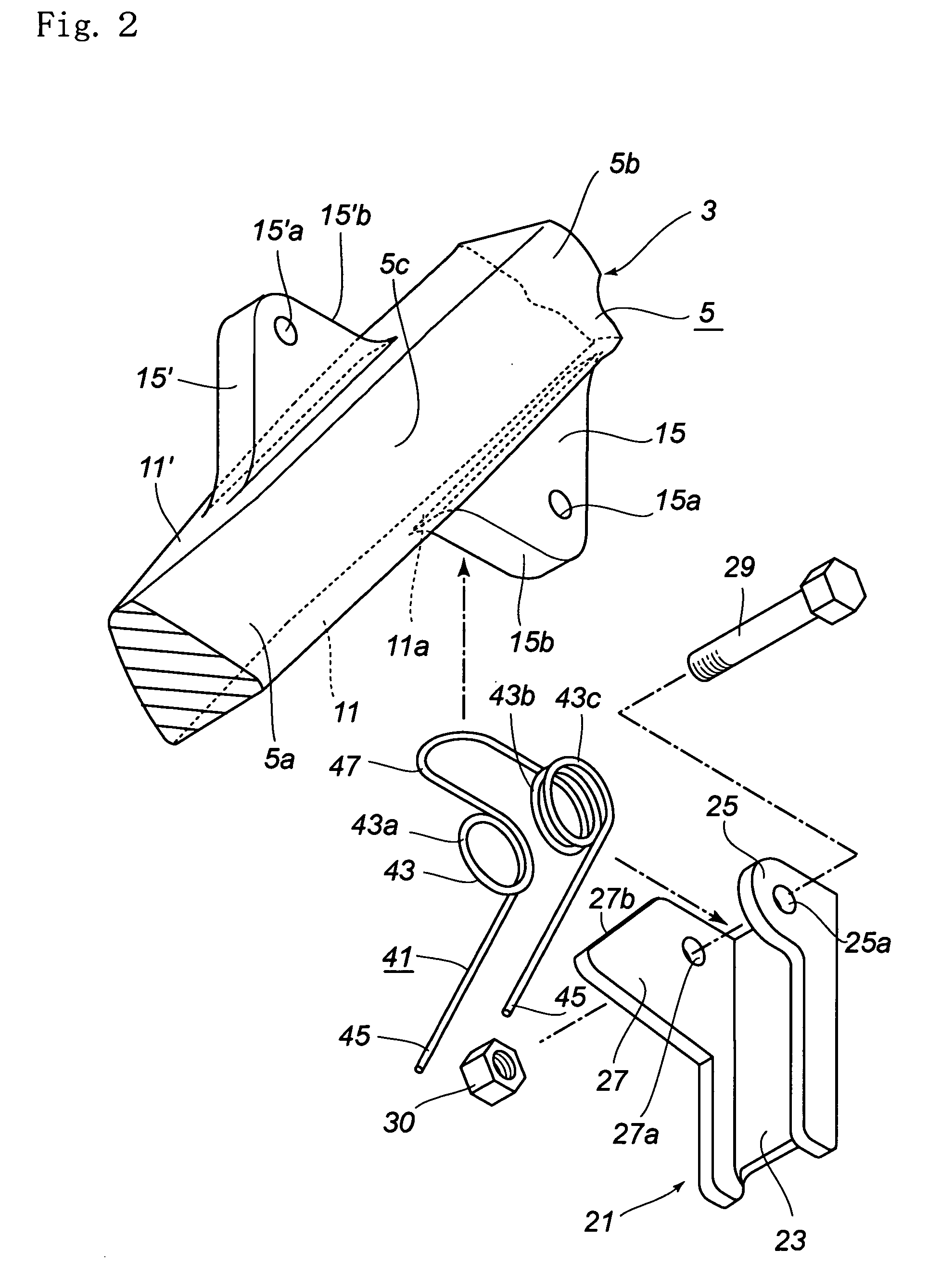
[0051] The rope hook 1 of the present invention comprises a body 3 including a pair of hook shaped rope catches 7, 7′ and a pair of off-the-hook limiting levers 21, 21′ and complex springs 41 to urge the levers.

[A-1. The Body]

[0052] The body 3 is of generally substantially S shaped configuration, and includes a main frame 5, substantially J shaped upper and lower hook portions 7, 7′ extending in opposite direction from each end of the main frame respectively, and a pair of lev...

second embodiment

ii) The Second Embodiment

[A. Construction (see FIGS. 6-9)]

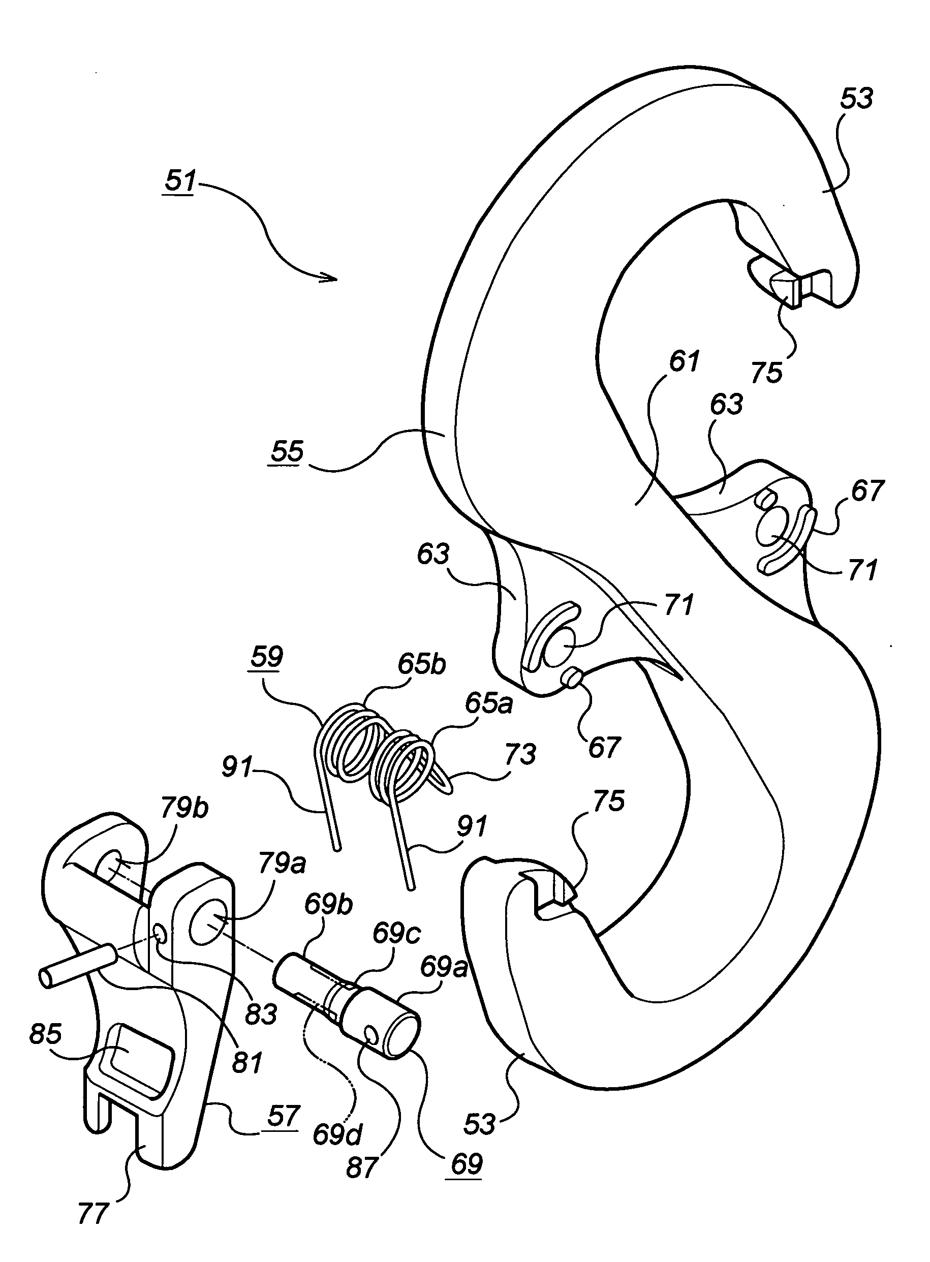
[0077] The rope hook of the second embodiment of the present invention is substantially equal to that of the first embodiment described with reference to FIGS. 1-5 so that the descriptions on the common features of these embodiments are set forth in summary, and the differences therebetween will now be described in detail.

[0078] The rope hook 51 is generally S shaped and includes a body 55 and a pair of hook shaped rope catches 53 provided at both ends of the body. A pair of off-the-hook limiting levers 57 are pivotally connected to the body 55. The levers are urged constantly by means of complex springs 59 toward the locked condition.

[0079] Each one of the hook portions 53, the levers 57, and the springs 59 are described with reference the drawings, since each one of these elements are formed point-symmetrically.

[A-1. The Body]

[0080] The body 55 includes an intermediate portion 61 the upper and lower ends of which are p...


PUM


Abstract

A rope hook with an off-the-hook limiting lever connected to a lever support of a body to be able to pivot in a front to rear direction and to shift laterally within a predetermined range. The lever is urged frontward (in a closed direction) and leftward (in a locked direction) by a complex spring. In the locked condition, the lever is prevented from pivoting rearward (in an opened direction) by a stopper edge of the arm engaging with a stopper surface of the body. In this connection, when it is intended to release the locked condition, it is necessary to push the lever rightward to disengage the stopper edge with the stopper surface and then push the lever rearward to pivot it in the opened position. In other words, the lever remains unopened unless two forces perpendicular to each other are applied sequentially to the lever.

Description

BACKGROUND OF THE INVENTION [0001] 1. Technical Field [0002] The present invention relates to a rope hook. More particularly, the invention relates to a rope hook including a body having rope catches of substantially hook shape for disconnectably receiving ropes and off-the-hook limiting levers pivotally connected to the body. [0003] 2. Description of the Prior Art [0004] There are various kinds of slinging means such as hanging hooks and rope connectors used in the crane or the winch, and a hooked portion of the turnbackle. These slinging means and hanging hooks include in many cases one or more catching means of C or U shape to which a rope or a portion of the rope spliced into looped shape is to be threaded. [0005] Some of these slinging means further include a off-the-hook limiting lever (referred simply as “a stop”, “a snap lever” or “a metal piece”). [0006] An example of the rope hook (a) of the prior art including off-the-hook limiting lever will now be described with referen...

Claims


Application Information

Patent Timeline
IPC IPC(8): F16B45/02B66C1/34B66C1/36
CPCY10T24/45346B66C1/36
Inventor KIMURA, SHIGEJIRO
Owner NIICHI
Why Eureka
Try Eureka