System and apparatus for radial optical distribution

a technology of optical distribution and radial system, applied in the direction of optical elements, ring-type electromagnetic networks, instruments, etc., can solve the problems of general circuit administration and storage, accurate routing of fiber pigtails, and concerns about congestion and tangling of fiber pigtails, etc., to improve fiber organization and routing management.

Active Publication Date: 2006-07-27
FURAKAWA ELECTRIC NORTH AMERICA INC
View PDF15 Cites 76 Cited by
  • Summary
  • Abstract
  • Description
  • Claims
  • Application Information

AI Technical Summary

Benefits of technology

[0009] The invention is embodied in an apparatus and system for managing and radially distributing optical fibers from a first location, such as a central office, to a plurality of destination locations, such as homes within a neighborhood. The apparatus includes a distribution panel having a central hub or ring, and both a plurality of optical input elements and a plurality of optical output elements disposed radially around the central hub. The optical input elements split the fibers in main feeder fiber bundles coupled from the first location into a plurality of individual fibers that are routed to the central hub. The central hub radially distributes the plurality of individual fibers to appropriate optical output elements. The optical output elements are coupled to destination fibers routed to the plurality of destination locations. The radial configuration of the apparatus provides a central breakout point for fiber distribution, thus improving fiber organization and routing management compared to conventional routing and distribution systems.

Problems solved by technology

With such a relatively large number of individual fiber pigtails, congestion and tangling of the fiber pigtails become concerns.
Also, accurate routing of the fiber pigtails and general circuit administration and storage are issues with these types of packaging structures.

Method used


Image

  • System and apparatus for radial optical distribution
  • System and apparatus for radial optical distribution
  • System and apparatus for radial optical distribution

Examples


Embodiment Construction

[0014] In the following description like reference numerals indicate like components to enhance the understanding of the invention through the description of the drawings. Also, although specific features, configurations and arrangements are discussed hereinbelow, it should be understood that such is done for illustrative purposes only. A person skilled in the relevant art will recognize that other steps, configurations and arrangements are useful without departing from the spirit and scope of the invention.

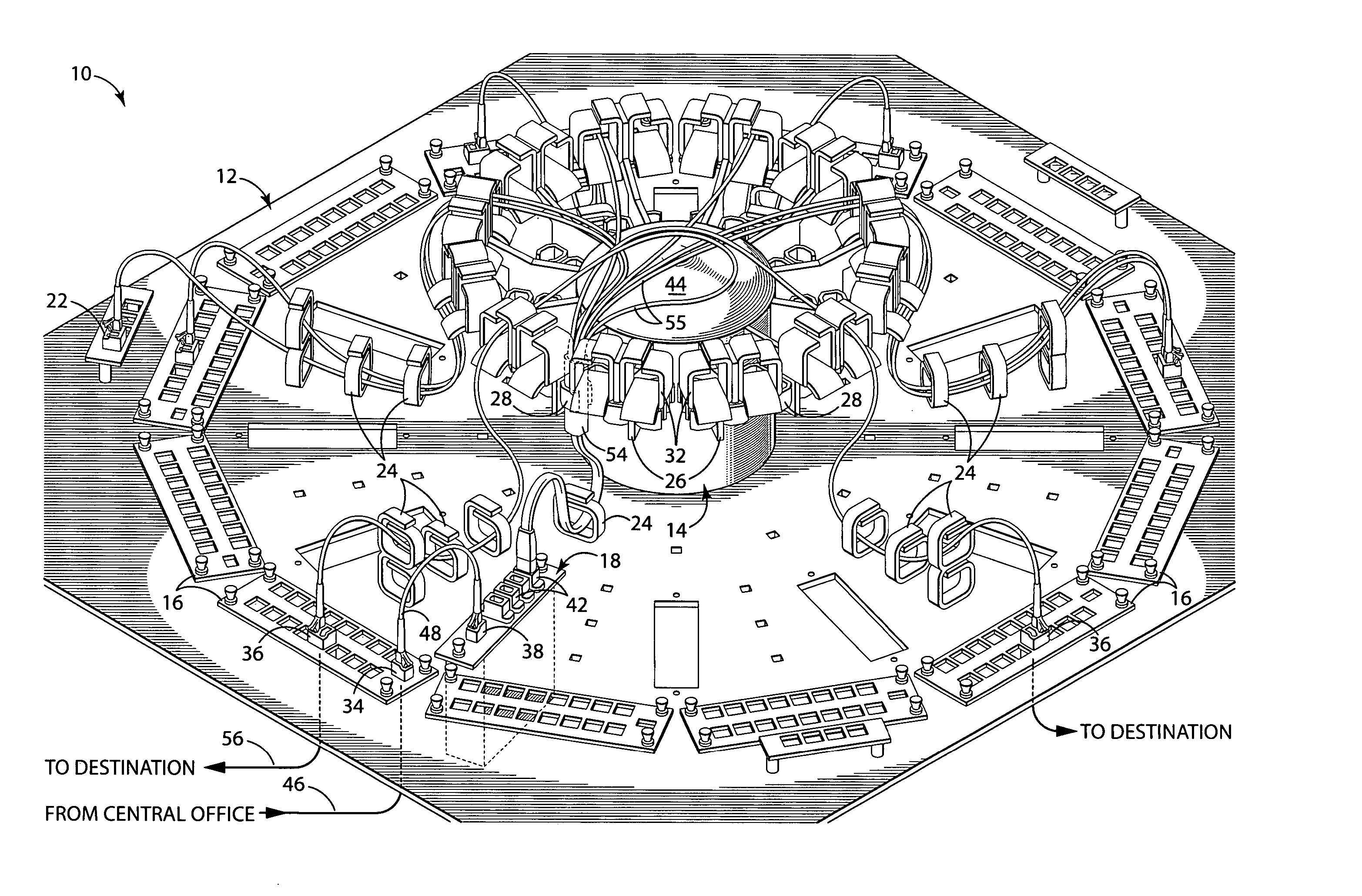
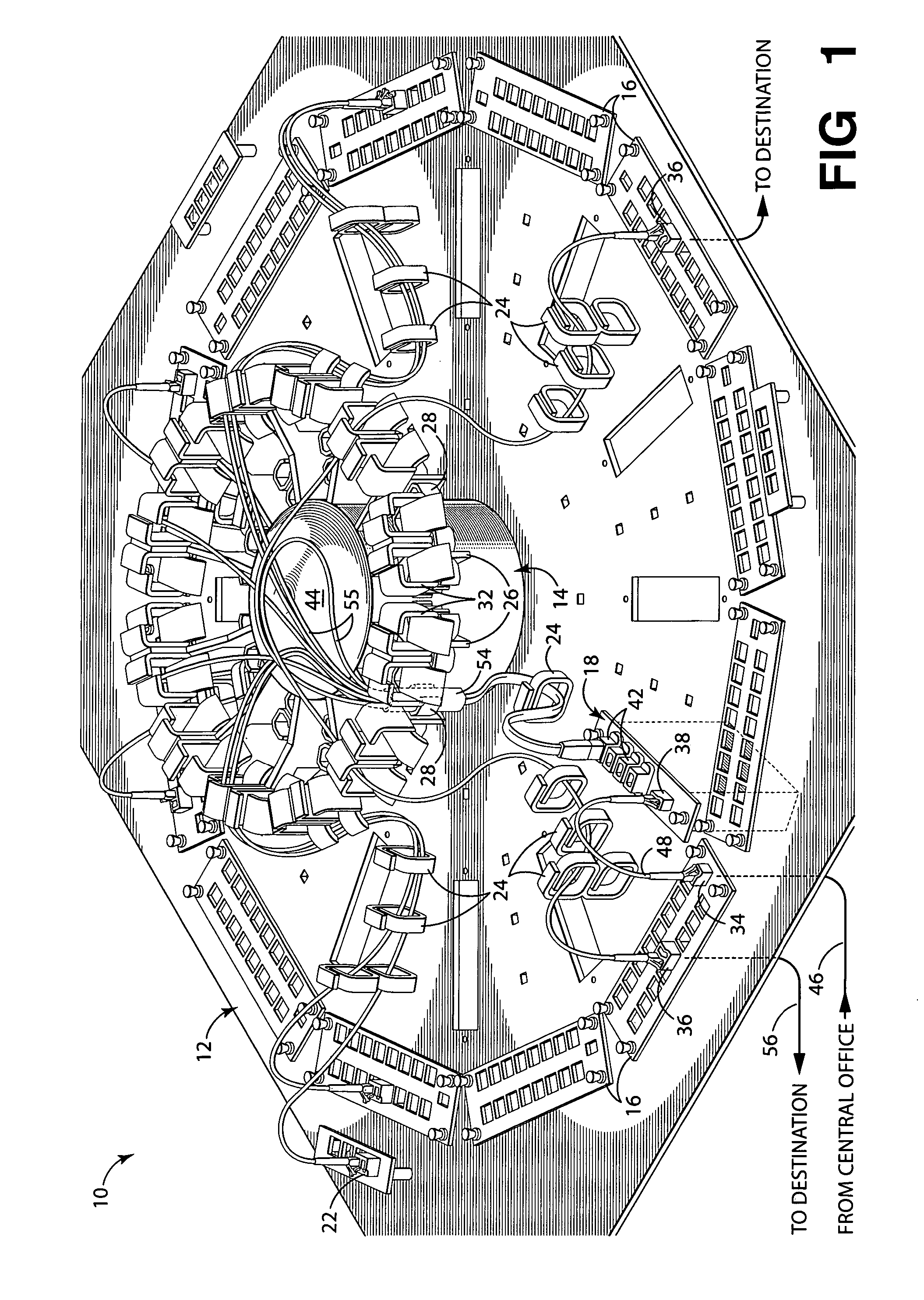
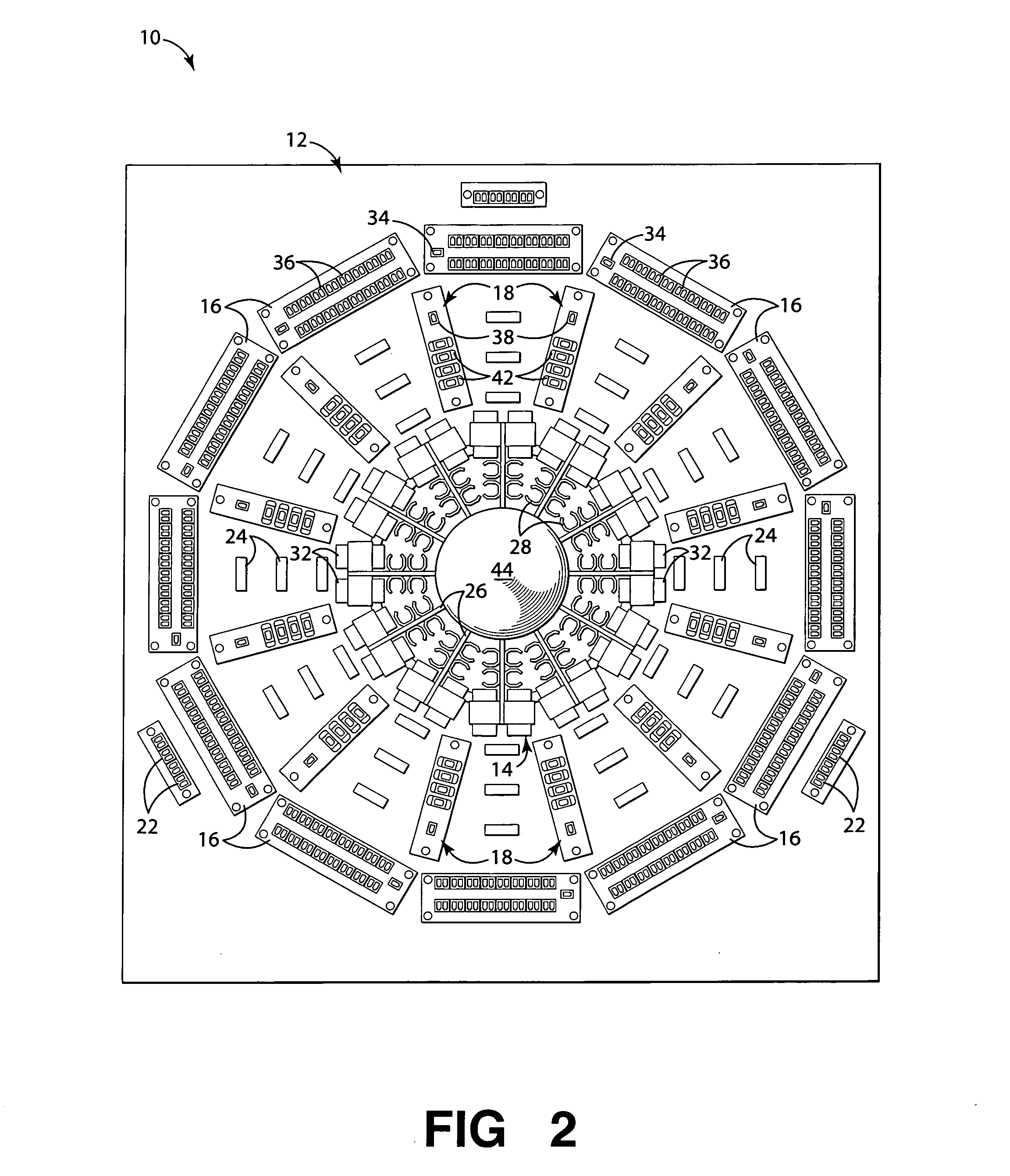
[0015] Embodiments of the invention include a radial optical management and distribution system architecture and apparatus that allows optical fibers from a first (source) location, such as a central office main feeder fiber bundle, to be routed to a plurality of second (destination) locations, such as feeder lines to homes within a neighborhood. The distribution apparatus includes at least one input element that receives optical fibers from the first location and at least one o...


PUM


Abstract

Embodiments of the invention include an apparatus and system for managing and radially distributing optical fibers from a first location, such as a central office, to a plurality of destination locations, such as homes within a neighborhood. The apparatus includes a distribution panel having a central hub or ring, and both a plurality of optical input elements and a plurality of optical output elements disposed radially around the central hub. The optical input elements split the fibers coupled from the first location into a plurality of individual fibers that are routed to the central hub. The central hub radially distributes the plurality of fibers to appropriate optical output elements, which are coupled to destination fibers routed to the plurality of destination locations. The radial configuration of the apparatus provides a central breakout point for fiber distribution, thus improving fiber organization and routing management compared to conventional routing and distribution systems.

Description

BACKGROUND OF THE INVENTION [0001] 1. Field of Invention [0002] The invention relates to the distribution of optical signals. More particularly, the invention relates to radial systems, apparatus and methods for distributing optical signals. [0003] 2. Description of Related Art [0004] One of the most important recent developments in the field of fiber optic communications is the emergence of the feasibility of fiber management and distribution systems, arrangements and devices for delivering optical fiber signals to a particular location or group of locations. Such applications typically are referred to as Fiber to the x (FTTx) applications. One of the more popular FTTx applications is Fiber to the Premises (FTTP) or Fiber To The Home (FTTH), in which optical signal capabilities are routed from a central office or other distribution location to a plurality of homes in that particular location via optical fiber and one or more optical connectors and / or other optical connection device...

Claims


Application Information

Patent Timeline
Patent Type & Authority Applications(United States)
IPC IPC(8): G02B6/00H04B10/272
CPCG02B6/4452H04B10/271H04B10/272H04B10/275G02B6/46
Inventor FEUSTEL, CLAY A.HENDRICKSON, DANIELZHANG, HONGBO
Owner FURAKAWA ELECTRIC NORTH AMERICA INC
Why Eureka
Try Eureka