Lock and release mechanism for a sternal clamp

a technology which is applied in the field of sternal clamp and release mechanism for telescoping or sliding paired members, can solve the problems of cumbersome locking mechanism, inability to releasably remove mechanism, and difficult adjustment and removal, and achieve the effect of preventing relative movement of the clamp member

Inactive Publication Date: 2006-07-27
GABELE LORENZ
View PDF99 Cites 178 Cited by
  • Summary
  • Abstract
  • Description
  • Claims
  • Application Information

AI Technical Summary

Benefits of technology

[0007] The lock and release mechanism comprises an engagement means and a status control means. The engagement means comprises a spring biased engagement arm pivotally mounted to one of the clamp members. The engagement arm is provided with engagement teeth that cooperate with engagement teeth of a ratchet bar disposed on the other of the clamp members. The status control means controls the position and freedom of movement of the engagement arm, such that the status control means can be adjusted to determine whether the device is in the locked, closing or open status. The status control means comprises a rotating member having a cam follower disposed within a cam opening provided in the engagement arm. The cam opening is of a non-symmetrical shape, such that with the cam following oriented in a first position, designated as the open status, the engagement arm is pivoted and held free of the clamp engagement teeth such that relative movement of the two clamp members is not precluded or controlled in either direction. With the cam follower oriented in a second position, designated as the closing status, the teeth of the engagement arm mate with the clamp engagement teeth, but the engagement arm is allowed limited travel away from the clamp engagement teeth such that the clamp members can be slid together. With the cam follower oriented in a third position, designated as the locked status, the teeth of the engagement arm mate with the clamp engagement teeth, but the engagement arm is prevented from traveling away from the clamp engagement teeth, thereby preventing relative movement of the clamp members in either direction. The status of the device can be changed from one to the other at any time.

Problems solved by technology

A problem with the known devices is that the locking mechanisms utilized to maintain the sternal clamp in the compressed or contracted position are typically cumbersome, difficult to adjust and difficult to remove.
Some mechanisms are not releasable at all once the clamp has been compressed.
Some mechanisms do not allow the clamp members to be extended once the device has been compressed.
All of these problems are exacerbated in emergency situations where immediate removal of the sternal clamp is required, such that in many cases destruction of the clamp by sawing or the like is the only suitable method for rapid access.

Method used


Image

  • Lock and release mechanism for a sternal clamp
  • Lock and release mechanism for a sternal clamp
  • Lock and release mechanism for a sternal clamp

Examples


Embodiment Construction

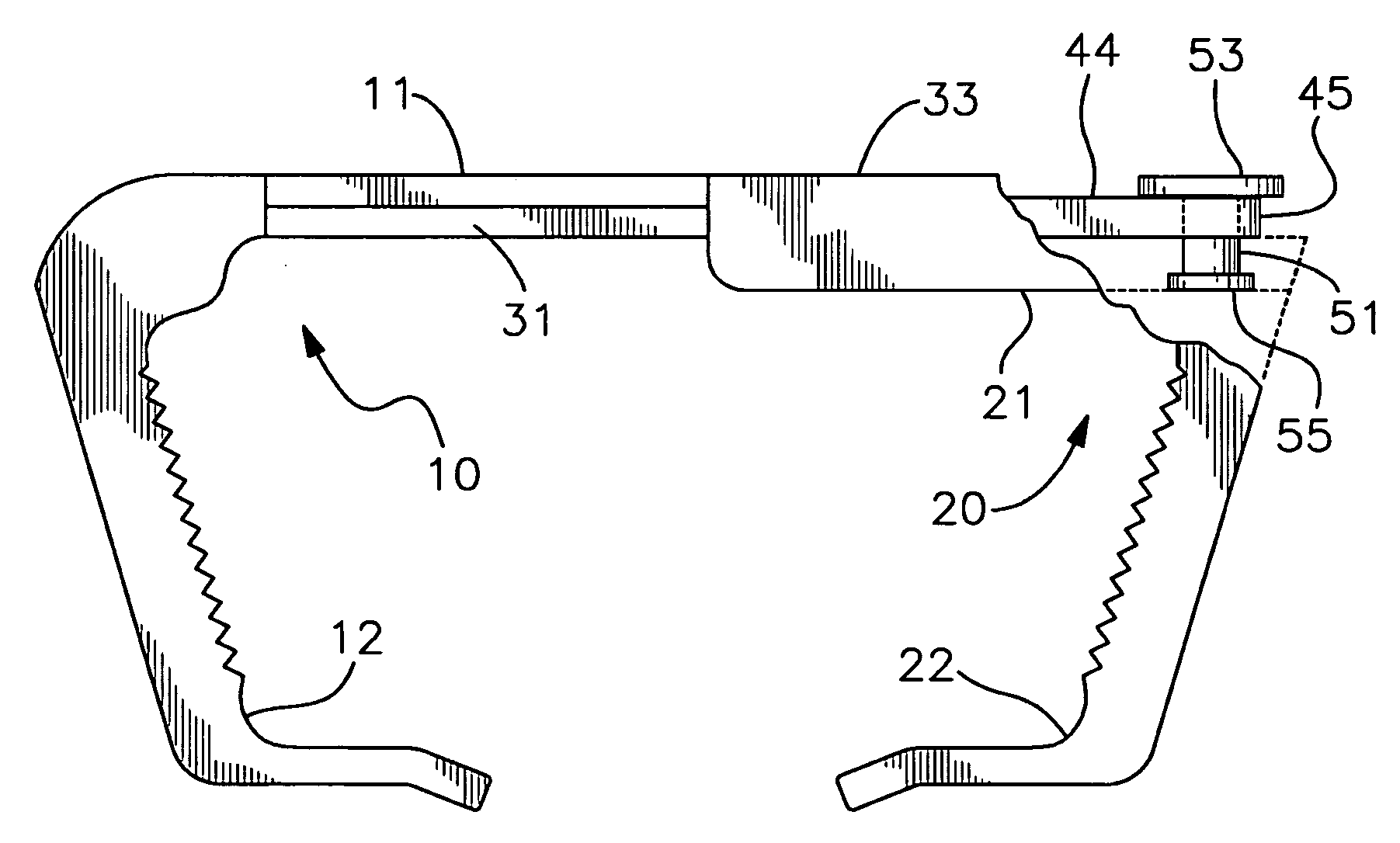
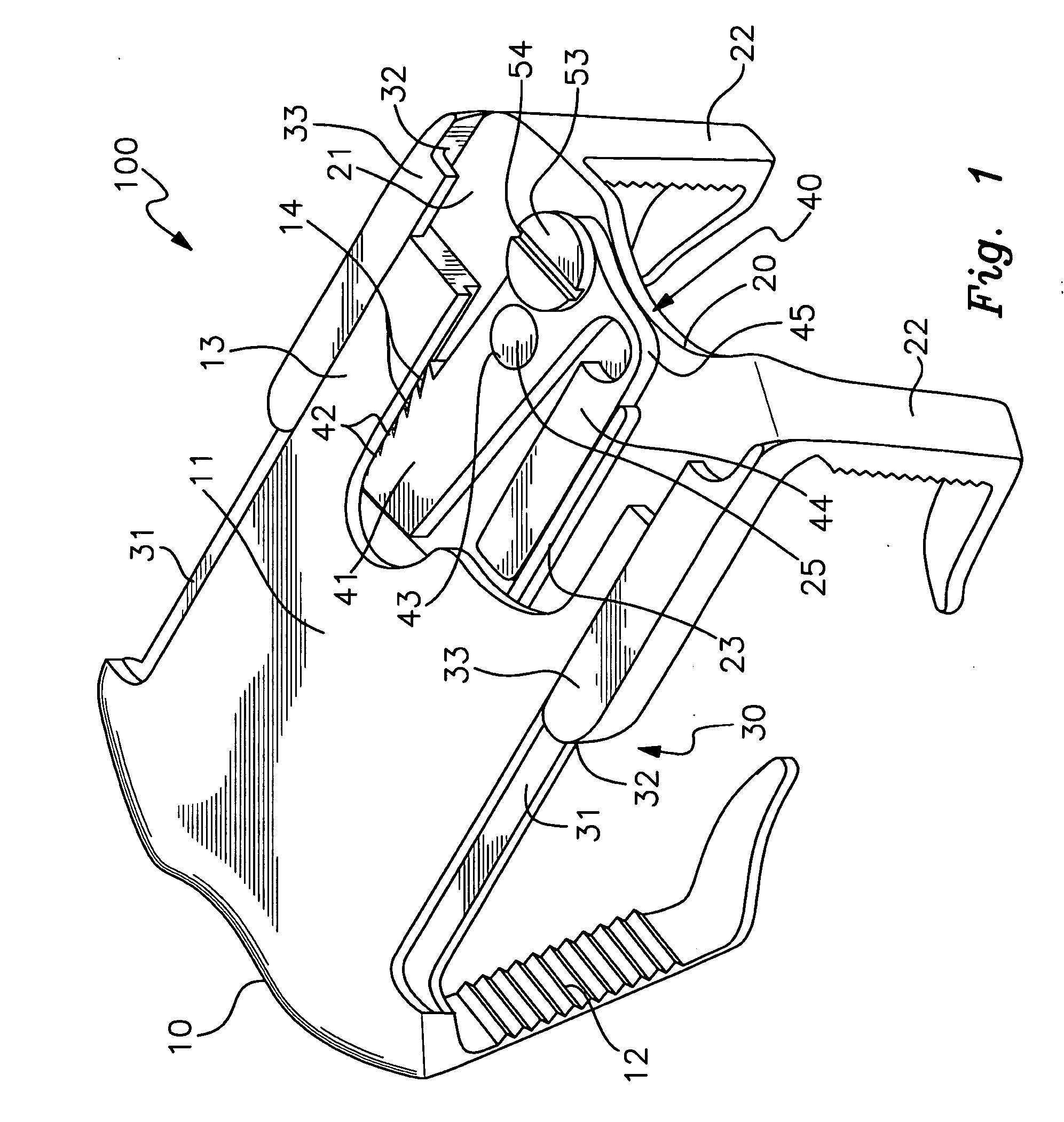
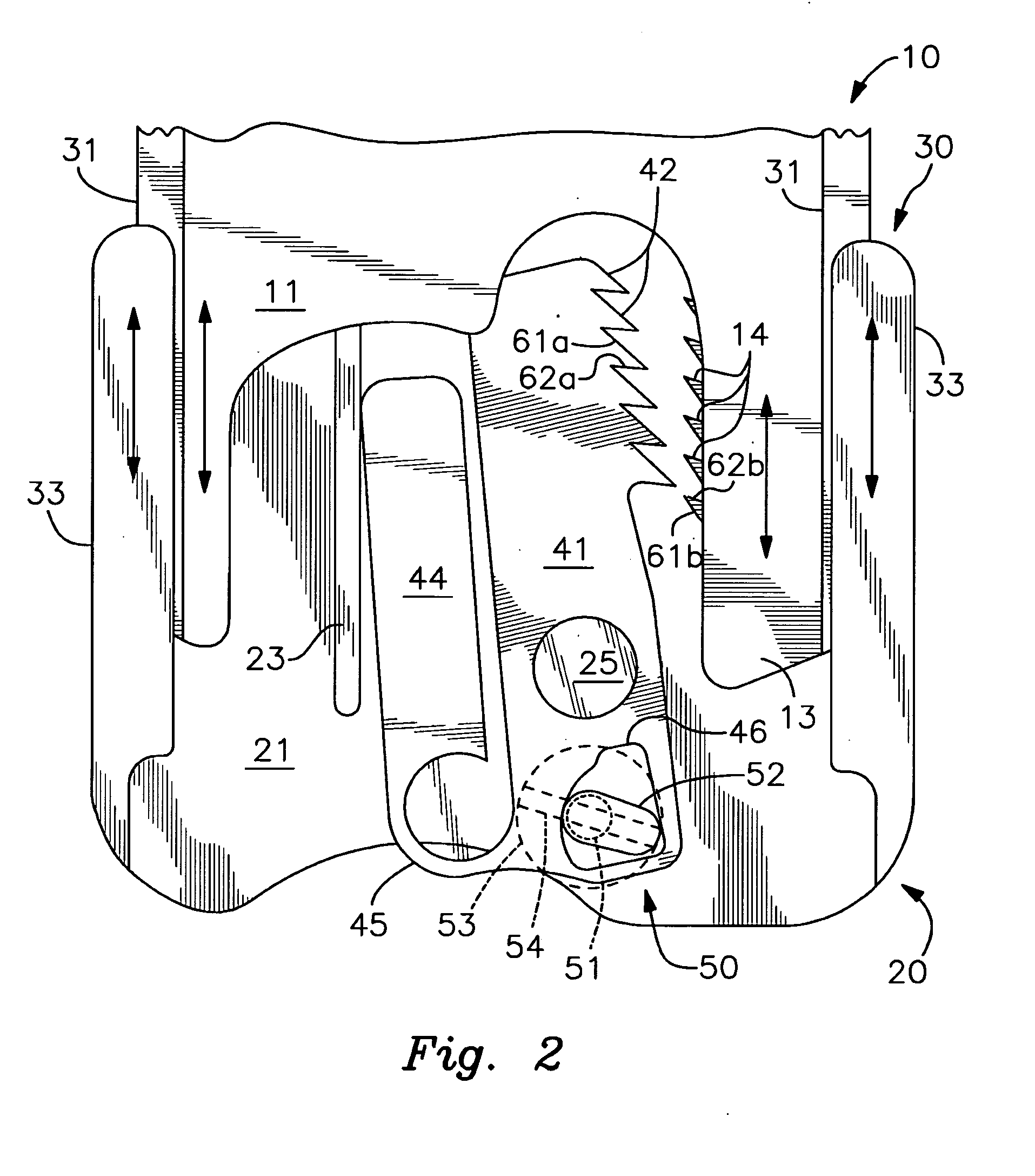
[0015] With reference to the drawings, the invention will now be described in detail with regard for the best mode and the preferred embodiment. In general, the invention is a locking and release mechanism and a sternal clamp comprising this mechanism, the sternal clamp comprising a pair of opposing clamp members that engage in a sliding or telescoping manner, whereby the sternal clamp can be placed into an open, closing or locked status. In the open status, the sternal clamp can be lengthened or shortened by bringing together or pulling apart the paired clamp members, as well as disassembled by fully separating the clamp members from each other. In the closing status, the clamp members can only be pushed together such that the sternal clamp can be shortened, but the clamp members cannot be pulled apart to lengthen the sternal clamp. In the locked status, the clamp can be neither lengthened nor shortened as relative movement of the clamp members is precluded.

[0016] The sternal clam...


PUM


Abstract

An engagement mechanism for a sternal clamp, the mechanism allowing for an open status where the clamp may be lengthened or shortened, a closing status where the clamp may only be shortened, and a locked status where the clamp cannot be lengthened or shortened.

Description

[0001] This application claims the benefit of U.S. Provisional Patent Application Ser. No. 60 / 646,732, filed Jan. 25, 2005.BACKGROUND OF THE INVENTION [0002] The invention relates generally to the field of lock and release mechanisms for telescoping or sliding paired members, more particularly relates to such mechanisms that allow the paired members to have three operational settings—a locked status precluding relative movement of the member pair, a closing status allowing relative movement of the paired members only in the direction toward each other to shorten the overall length of the combination of members, and a free travel status whereby the paired members can be moved in either direction relative to each. More particularly, the invention relates to such devices that utilize engaging opposing teeth of a ratchet bar type of construction. In particular, the invention is applicable for use with a sternal clamp device, and such an application shall be utilized to describe the inve...

Claims


Application Information

Patent Timeline
Patent Type & Authority Applications(United States)
IPC IPC(8): A61B17/58
CPCA61B17/8004A61B17/823A61B17/8076
Inventor GABELE, LORENZ
Owner GABELE LORENZ
Why Eureka
Try Eureka