Clutch actuator for straddle-type vehicle

a technology of straddle-type vehicles and actuators, which is applied in the direction of fluid-actuated clutches, clutches, non-mechanical actuated clutches, etc., can solve the problems of insufficient stability of prior clutch actuators with the clutch engaged, and achieve the effect of optimizing the weight balance, no torque, and small siz

Active Publication Date: 2006-08-03
YAMAHA MOTOR CO LTD
View PDF11 Cites 47 Cited by
  • Summary
  • Abstract
  • Description
  • Claims
  • Application Information

AI Technical Summary

Benefits of technology

[0011] In an additional preferred mode, the auxiliary biasing mechanism is arranged so as to produce a torque on the rotating member in a direction promoting clutch engagement at least when the rotating member lies in a position corresponding to the engaged state of the clutch. The auxiliary biasing mechanism can further be arranged to produce a torque on the rotating member in a direction promoting clutch disengagement at least when the rotating member lies in a position corresponding to the disengaged state of the clutch. Furthermore, the clutch operating member can be arranged so as to produce substantially no torque on the rotating member when the rotating member lies in a position corresponding to the engaged state. Therefore, it is possible to rotationally drive the rotating member with a relatively small torque, thus enabling making an actuator (e.g., a motor) small in size. As a result, it is possible to lighten a straddle-type vehicle and to optimize its weight balance.

Problems solved by technology

As a result, such prior clutch actuators can have insufficient stability with the clutch engaged.

Method used


Image

  • Clutch actuator for straddle-type vehicle
  • Clutch actuator for straddle-type vehicle
  • Clutch actuator for straddle-type vehicle

Examples


Embodiment Construction

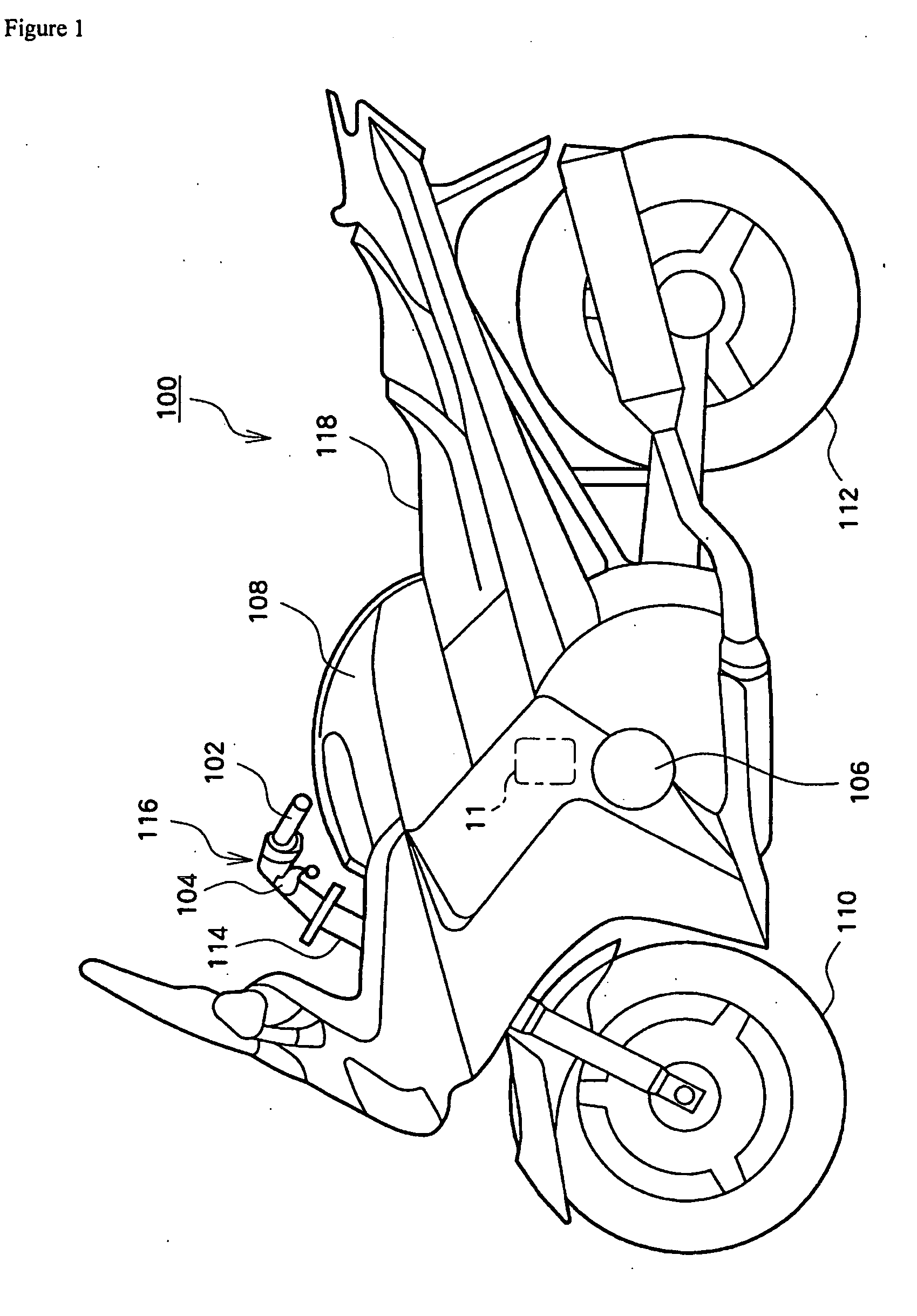
[0022]FIG. 1 is a side view showing an outward appearance of a motorcycle that includes a clutch actuator mechanism 11, which is configured in accordance with a preferred embodiment of the present invention. The motorcycle 100 shown in the figure is an example of a straddle-type vehicle and comprises front and rear wheels 110, 112. A handlebar 116 extends transversely (i.e., perpendicular to a vehicle traveling direction) and is mounted to a top of a front fork 114. The front wheel 110 is connected to a lower portion of the front fork 114. A grip 102 and a clutch lever 104 are disposed at one end of the handlebar and an accelerator grip and a brake lever (not shown) are disposed at the other end of the handlebars. Also, a seat 118 is provided on an upper side of the motorcycle 100 and positioned such that a rider can get on the motorcycle 100, straddling the seat 118, and grasp the handlebar. The overall construction of the motorcycle 100 is substantially the same in construction as...


PUM


Abstract

A clutch actuator is provided to stabilize a state of clutch engagement. A rotating member is rotationally driven on a rotating shaft by a motor. A clutch operating member includes two ends. One end of the clutch operating member is pushed by a push force of a clutch spring and the other end is pivotally supported on the rotating member by a shaft. The clutch operating member disengages the clutch when moved in a direction against the force of the clutch spring. An auxiliary biasing mechanism also acts on the rotating member. One end of the auxiliary biasing member is supported on a vehicle side and the other end is pivotally supported on the rotating member by a shaft. The auxiliary biasing member can include a compressible coil spring. The rotating member rotates in a first direction to move the clutch operating member in a direction of clutch engagement. When the clutch is engaged, the combined torque on the rotating member, which is produced by forces asserted by the auxiliary biasing mechanism and the clutch operating member, bias the rotating member in the first direction.

Description

CROSS-REFERENCE TO RELATED APPLICATIONS [0001] The present application is based on and claims priority under 35 U.S.C. § 119 to Japanese Patent Application No. 2204-359227, filed on Dec. 10, 2005, the entire contents of which is expressly incorporated by reference herein. BACKGROUND OF THE INVENTION [0002] 1. Field of the Invention [0003] The present invention relates to a clutch actuator for a straddle-type vehicle and, more particular, to a clutch actuator mechanism to effect clutch engagement and disengagement with a smaller motor size. [0004] 2. Description of the Related Art [0005] Clutch actuators often use a motor to cause a clutch mounted on a vehicle to move between an engaged state and a disengaged state. Normally, a biasing force acts to engage the clutch. In order to disengage the clutch, the motor must increase its output to overcome the biasing force. Some of such clutch actuators, such as that disclosed in Japanese Patent Publication No. 2000-501826, comprises elastic...

Claims


Application Information

Patent Timeline
Patent Type & Authority Applications(United States)
IPC IPC(8): F16D29/00
CPCF16D28/00
Inventor KOSUGI, MAKOTO
Owner YAMAHA MOTOR CO LTD
Why Eureka
Try Eureka