Electric hydraulic ring-plug pump

A technology of electro-hydraulic pumps and ring plugs, which is applied in the direction of pumps, multi-cylinder pumps, pump components, etc., can solve the problems of low frequency response of direct-drive volume control systems, and achieve the effects of light weight, cost reduction, and low noise

Active Publication Date: 2015-12-23
HARBIN INST OF TECH
View PDF6 Cites 2 Cited by
  • Summary
  • Abstract
  • Description
  • Claims
  • Application Information

AI Technical Summary

Problems solved by technology

[0004] The purpose of the present invention is to provide a ring plug electro-hydraulic pump to solve the problem of low frequency response of the direct drive volume control system

Method used


Image

  • Electric hydraulic ring-plug pump
  • Electric hydraulic ring-plug pump
  • Electric hydraulic ring-plug pump

Examples


specific Embodiment approach 1

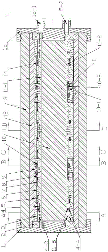
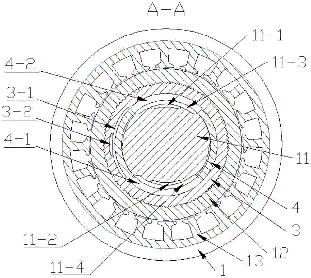
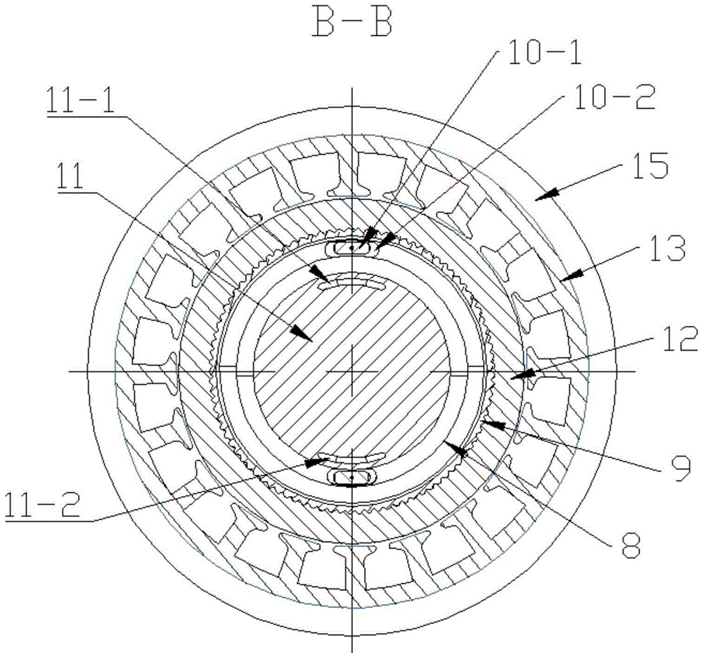
[0014] Specific implementation mode one: combine figure 1 , figure 2 , image 3 , Figure 4 , Figure 5 and Figure 6 As shown, the technical solution of this specific embodiment is illustrated, which includes a sealing end cover 1, two bearings 2, three oil distribution rings 3, three oil distribution sleeves 4, four ring plug sleeves 5, and four ring plugs 6 , four guide rings 7, four swash plates 8, two drive rings 9, eight sets of shoe ejector rod mechanisms 10, hydraulic pump stator 11, motor rotor 12, motor stator 13, spring 14, interface end cover 15;

[0015] Each shoe ejector mechanism 10 is formed by the ejector rod 10-1 connected to the shoe 10-2; the hydraulic pump stator 11 is sequentially covered with a bearing 2, an oil distribution sleeve 4, a Spring 14, a ring plug 6, a guide ring 7, a swash plate 8, a drive ring 9, a swash plate 8, a guide ring 7, a ring plug 6, a spring 14, an oil distribution sleeve 4, a spring 14. A ring plug 6, a guide ring 7, a sw...


PUM


Abstract

The invention relates to an electric hydraulic ring-plug pump, and belongs to the technical field of hydraulic power element structures. A bearing, an oil distribution sleeve, a spring, a ring plug, a guiding ring, a tilting disc, a driving ring, a tilting disc, a guiding ring, a ring plug, a spring, an oil distribution sleeve, a spring, a ring plug, a guiding ring, a tilting disc, a driving ring, a tilting disc, a guiding ring, a ring plug, a spring, an oil distribution sleeve and a bearing sequentially sleeve a hydraulic pump stator of the electric hydraulic pump from left to right, and abut against each other. The electric hydraulic pump disclosed by the invention is simple in structure and adopts few movable parts, so that the reliability of the electric hydraulic pump is improved, and the cost of the electric hydraulic pump is reduced; the electric hydraulic pump is a two-way hydraulic pump; the distance between a high-pressure oil cavity and a low-pressure oil cavity is long, and equal to the heights of the two ring plugs, and the internal leakage between the high-pressure oil cavity and the low-pressure oil cavity is small; the rigidity of the springs of the hydraulic pump is high, so that the self-sucking capability of the hydraulic pump is high; the electric hydraulic pump is provided with few rotating parts, so that the rotating inertia is small.

Description

technical field [0001] The invention belongs to the technical field of hydraulic power element structure. Background technique [0002] Hydraulic systems play an important role in modern industrial technology. At present, the hydraulic pump used in the hydraulic system is connected to the motor through a coupling, which has the following shortcomings and deficiencies: noise and energy loss caused by the cooling fan of the motor; noise and vibration caused by the non-concentricity of the coupling; axial arrangement The installation and connection make the volume and quality larger; multiple connections and coordination reduce efficiency and reliability; there are external leakage paths, etc. In response to the shortcomings of the above hydraulic systems, many well-known companies and research institutions at home and abroad have developed shielded motor pumps and electro-hydraulic pumps. The shielded motor pump still adopts the traditional axial arrangement, and the motor a...

Claims


Application Information

Patent Timeline
Patent Type & Authority Applications(China)
IPC IPC(8): F04B1/16F04B17/03F04B53/00
Inventor 王茂坤齐雯雯姚学磊
Owner HARBIN INST OF TECH
Why Eureka
Try Eureka