Hanging type air monorail traffic system with connecting mechanism
A technology of monorail transportation and connecting mechanism, which is applied to the elevated railway system, motor vehicles, elevated railways, etc. with suspended vehicles, and can solve the problem of reducing the stability of the air rail operation, the comfort of passengers riding on the air rail, and the damage of the connecting mechanism and the car body Connecting parts, easy to shake and other problems, to achieve the effect of slowing down vibration, protecting quality and reducing vibration amplitude
- Summary
- Abstract
- Description
- Claims
- Application Information
AI Technical Summary
Problems solved by technology
Method used
Image
Examples
Embodiment 1
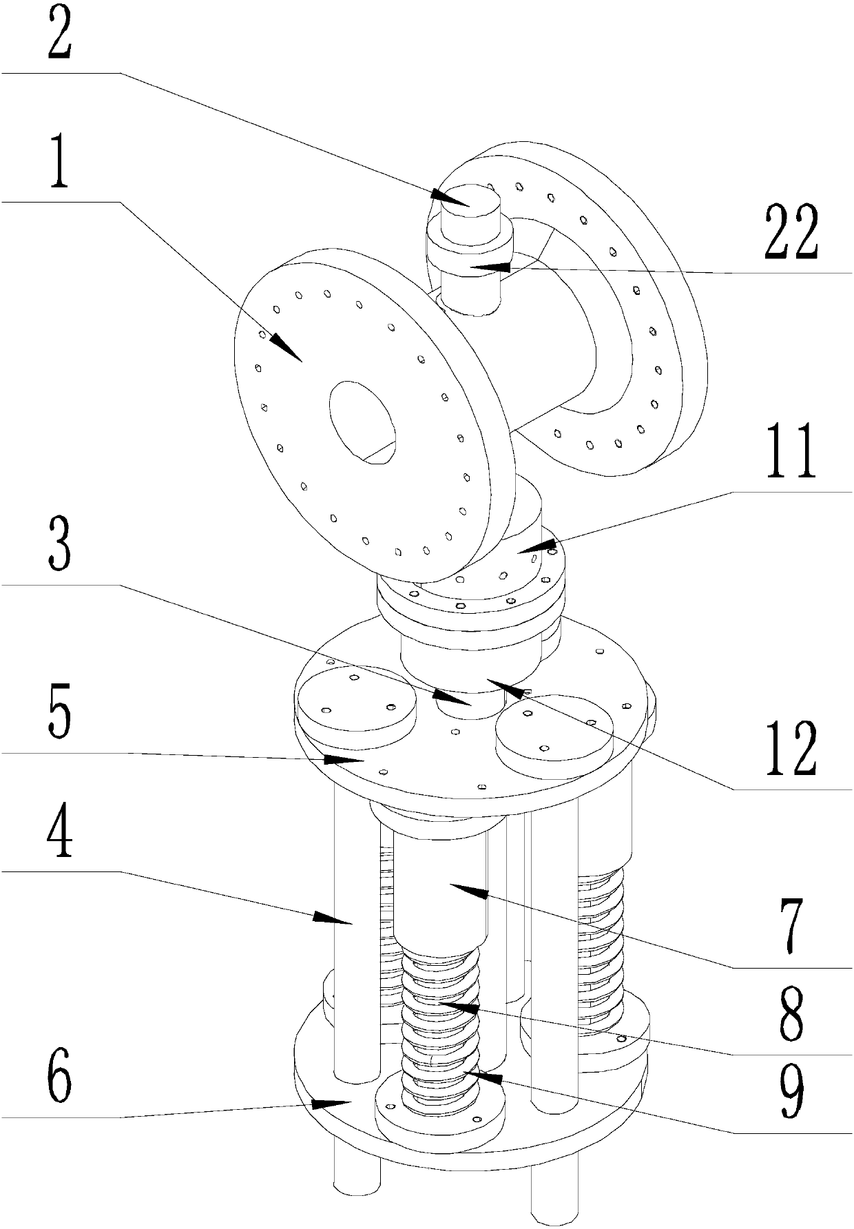
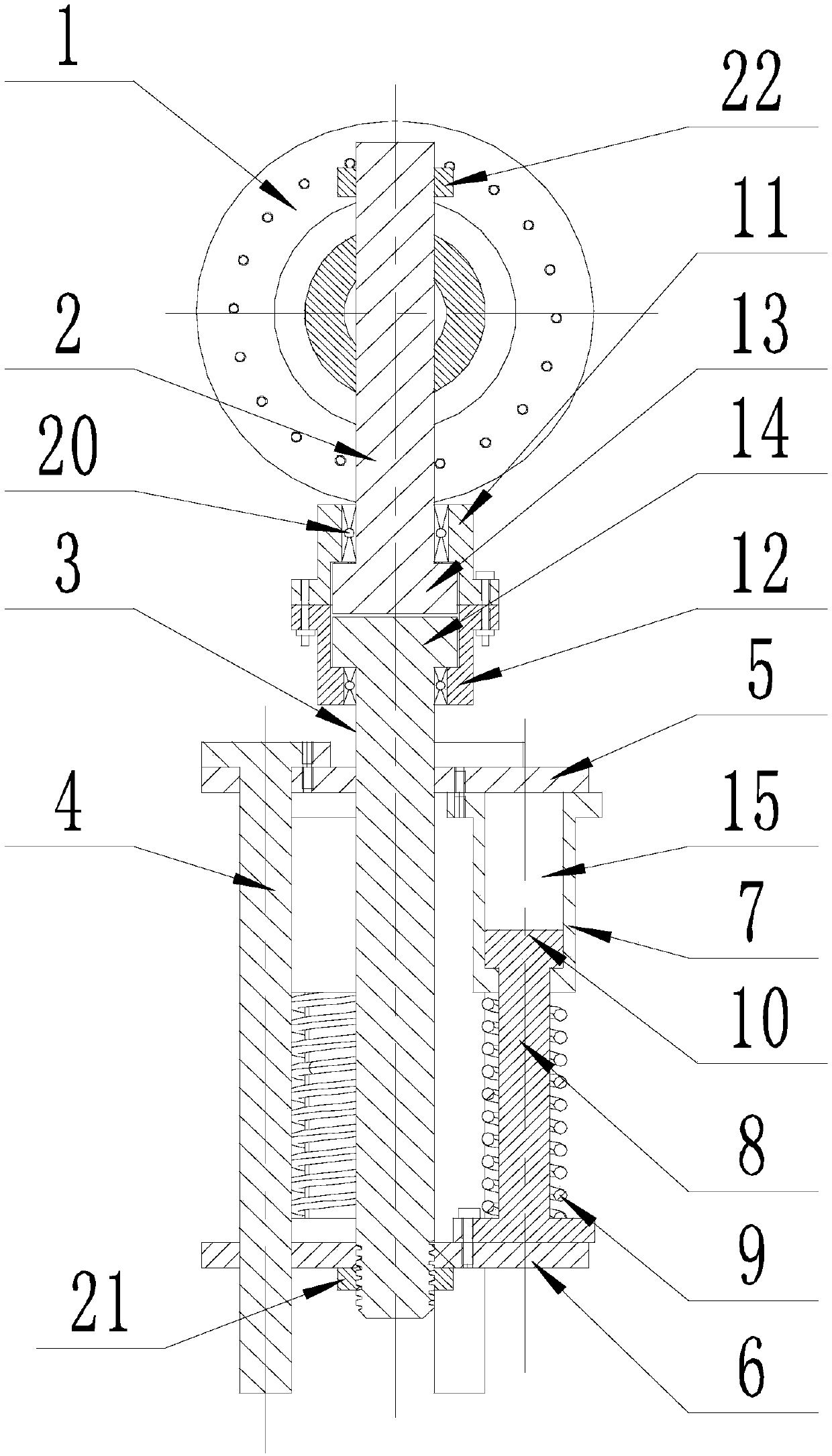
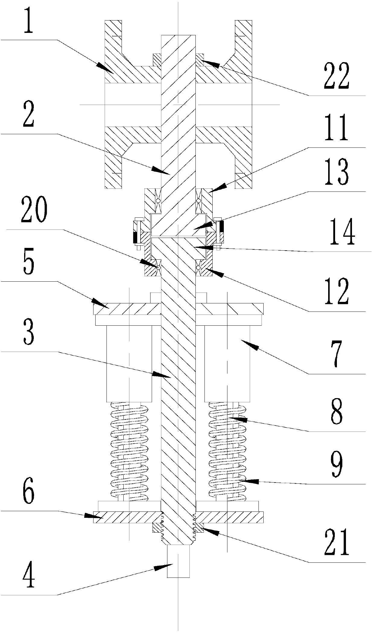
[0043] Such as Figure 1-Figure 6As shown, the connecting mechanism for the suspended aerial monorail transportation system of the present invention includes a pendant head 1 that connects the hub with the car body, and a suspension device is arranged between the pendant head 1 and the car body, and the suspension device includes a wire Shaft 2, main shaft 3, positioning shaft 4, load-bearing plate 5, silk plate 6 and telescopic assembly, the axes of the silk shaft 2, main shaft 3 and positioning shaft 4 are parallel to each other, and perpendicular to the load-bearing plate 5 and silk plate 6, the wire One end of the shaft 2 is connected to the end of the pendant head 1 close to the car body, and the other end of the wire shaft 2 is connected to one end of the main shaft 3 through the steering assembly. Both the wire shaft 2 and the main shaft 3 can rotate independently around their own axes relative to the steering assembly ;
[0044] The other end of the main shaft 3 moves...
Embodiment 2
[0049] This embodiment is based on Embodiment 1, and further explains the telescopic assembly.
[0050] Such as Figure 1-Figure 6 As shown, the connecting mechanism for the suspended aerial monorail transportation system of the present invention, the telescopic assembly includes a sleeve 7, a connecting rod 8 and a spring 9 that are sequentially connected and coaxial, and one end of the sleeve 7 is away from the bearing plate 5. One end of the pendant head 1 is connected, one end of the connecting rod 8 is inserted into the central hole 15 of the sleeve 7, the other end of the connecting rod 8 is connected with the end of the wire plate 6 close to the pendant head 1, and the spring 9 is sleeved on the On the connecting rod 8, and the end of the spring 9 close to the sleeve 7 is in contact with the end surface of the sleeve 7.
[0051] When the car body shakes, the load-bearing plate 5 moves downward, the sleeve 7 moves downward, and compresses the spring 9, which is deformed...
Embodiment 3
[0056] This embodiment is based on Embodiment 1 to further describe the steering assembly.
[0057] Such as Figure 1-Figure 6 As shown, the connecting mechanism for the suspended aerial monorail transportation system of the present invention, the steering assembly includes an upper steering platform 11 and a lower steering platform 12 connected in sequence, and the upper steering platform 11 is provided with an upper hole I16 that is sequentially communicated and coaxial. and the upper hole II17, the aperture of the upper hole II17 is larger than the aperture of the upper hole I16, and the end of the silk shaft 2 away from the pendant head 1 is provided with an upper connection platform 13 with a diameter greater than the diameter of the silk shaft 2, and the upper connection platform 13 cooperates with the upper hole II17, and the silk shaft 2 cooperates with the upper hole I16;
[0058] The lower turning table 12 is provided with a lower hole I18 and a lower hole II19 whic...
PUM
 Abstract
Description
Claims
Application Information
 - R&D
- Intellectual Property
- Life Sciences
- Materials
- Tech Scout
- Unparalleled Data Quality
- Higher Quality Content
- 60% Fewer Hallucinations
Browse by: Latest US Patents, China's latest patents, Technical Efficacy Thesaurus, Application Domain, Technology Topic, Popular Technical Reports.
© 2025 PatSnap. All rights reserved.Legal|Privacy policy|Modern Slavery Act Transparency Statement|Sitemap|About US| Contact US: help@patsnap.com


