Method of patterning cholesteric film and optical element having the cholesteric film patterned by the method
a technology of cholesteric film and optical element, which is applied in the direction of polarising elements, instruments, chemistry apparatus and processes, etc., can solve the problems of easy falling off, and achieve the effect of efficient and precise patterning of cholesteric film
- Summary
- Abstract
- Description
- Claims
- Application Information
AI Technical Summary
Benefits of technology
Problems solved by technology
Method used
Image
Examples
first embodiment
(Object to be Patterned)
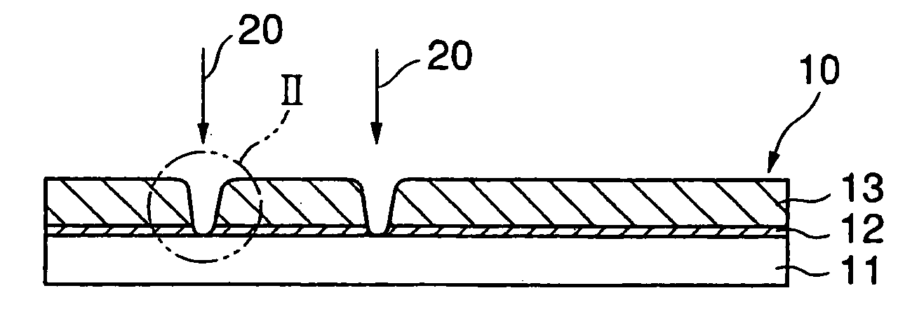
[0020] First of all, the object to which the method in a first embodiment of the present invention is applied will be explained by referring to FIG. 1. In this first embodiment of the invention, the object to be patterned is explained by taking, as an example, an original plate for optical elements that is used to produce a polarizing plate or the like.
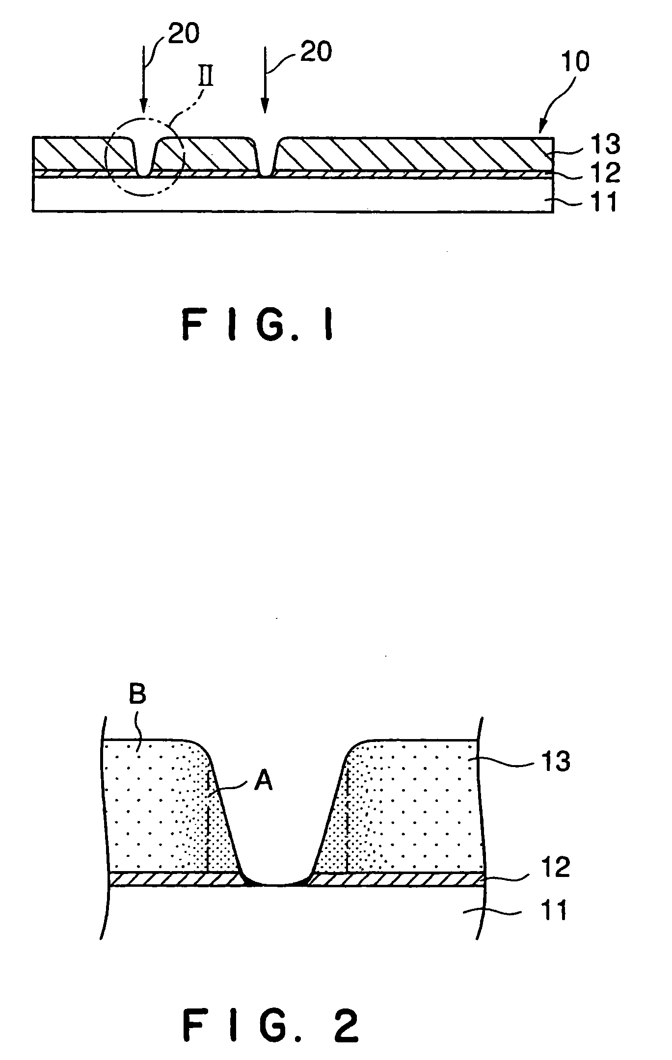
[0021] As shown in FIG. 1, an original plate for optical elements to which the method in the first embodiment of the invention is applied includes: a glass substrate 11; an alignment film 12 laminated to the glass substrate 11; and a cholesteric film 13 formed on the alignment film 12, oriented by the alignment-regulating action of the surface of the alignment film 12. The glass substrate 11 and the alignment film 12 constitute a base.
[0022] The cholesteric film 13 has the property of selecting polarized light (the property of splitting polarized light), which a component of light circularly polarized in on...
second embodiment
[0041] Next, the second embodiment of the present invention will be described. The second embodiment of the invention is the same as the foregoing first embodiment of the invention, except that laser light containing, as its main component, a component circularly polarized in the direction opposite to that of optical rotation of a component selectively reflected by the cholesteric film is used. Specifically, in the above explanation for the first embodiment, the description for the constitution of the object to be patterned (the item “Object to be Patterned”), and a part of the description for the method of patterning a cholesteric film (the item “Preparatory Step”) are applicable to the second embodiment as they are. Therefore, only the patterning step in the second embodiment of the method of patterning a cholesteric film will be hereinafter explained in detail.
(Patterning Step)
[0042] A cholesteric film 13 is formed on an alignment film 12 provided on a glass substrate 11 as sh...
example 1-1
[0047] 89 parts of a monomer containing, in its molecule, polymerizable acrylates at the both ends and spacers between mesogen existing at the center and the acrylates, having a nematic-isotropic transition temperature of 110° C., and 11 parts of a chiral agent having, in its molecule, polymerizable acrylates at the both ends were dissolved in toluene. To this toluene solution was added a photopolymerization initiator in an amount of 5% by weight of the above monomer.
[0048] On the other hand, a transparent glass substrate was spin-coated with polyimide dissolved in a solvent. After drying, the polyimide was allowed to form a film at 200° C. (film thickness 0.1 m). This film was rubbed in a definite direction to obtain an alignment film.
[0049] The glass substrate provided with the alignment film was set in a spin-coater, and the alignment film was spin-coated with the above-prepared toluene solution.
[0050] The toluene contained in the toluene solution was then evaporated at 80° C....
PUM
| Property | Measurement | Unit |
|---|---|---|
| temperature | aaaaa | aaaaa |
| temperature | aaaaa | aaaaa |
| isotropic transition temperature | aaaaa | aaaaa |
Abstract
Description
Claims
Application Information
 - R&D
- Intellectual Property
- Life Sciences
- Materials
- Tech Scout
- Unparalleled Data Quality
- Higher Quality Content
- 60% Fewer Hallucinations
Browse by: Latest US Patents, China's latest patents, Technical Efficacy Thesaurus, Application Domain, Technology Topic, Popular Technical Reports.
© 2025 PatSnap. All rights reserved.Legal|Privacy policy|Modern Slavery Act Transparency Statement|Sitemap|About US| Contact US: help@patsnap.com


