Method for forming pattern of organic electroluminescent element

a technology of electroluminescent elements and organic el elements, which is applied in the direction of electroluminescent light sources, electric lighting sources, solid-state devices, etc., can solve the problems that the irradiation of organic el elements with focus on only cumulative doses may not yield emission patterns, and achieve the effect of efficient patterning

Active Publication Date: 2017-02-14
MERCK PATENT GMBH
View PDF15 Cites 0 Cited by
  • Summary
  • Abstract
  • Description
  • Claims
  • Application Information

AI Technical Summary

Benefits of technology

[0022]According to one or more embodiments of the invention, light intensity and exposure time may be appropriately determined to achieve a predetermined emission luminance level. Accordingly, an organic electroluminescent element may be irradiated with light having a minimum cumulative dose, so as to efficiently pattern the organic electroluminescent element.

Problems solved by technology

Thus, irradiation of the organic EL element with focus on only cumulative dose may not yield an emission pattern having a predetermined gradation of emission luminance levels, depending on the relationship between light intensity and exposure time.

Method used


Image

  • Method for forming pattern of organic electroluminescent element
  • Method for forming pattern of organic electroluminescent element
  • Method for forming pattern of organic electroluminescent element

Examples


Embodiment Construction

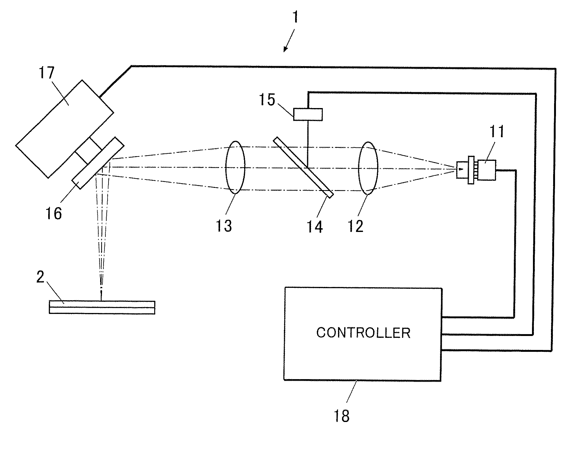
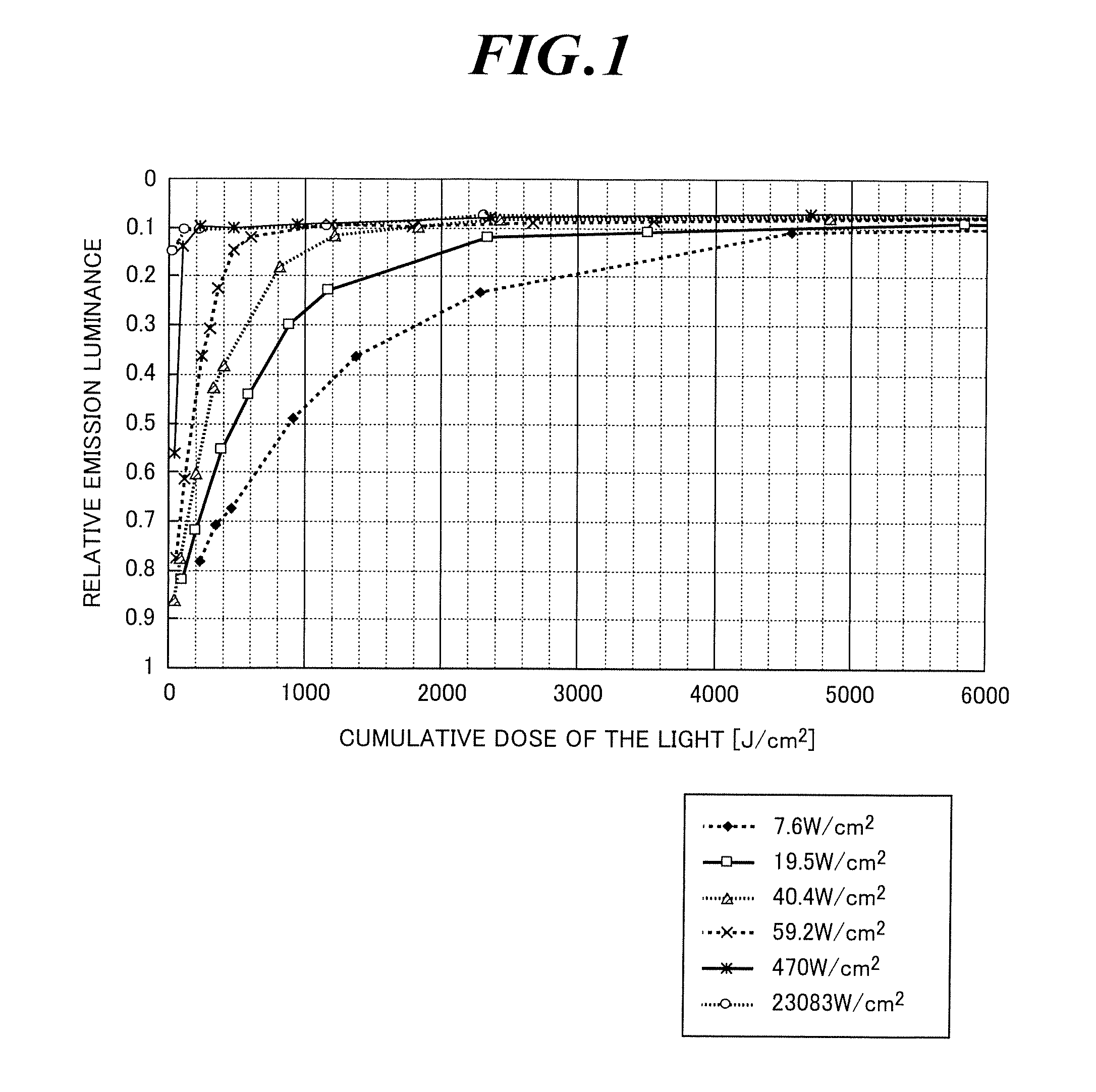
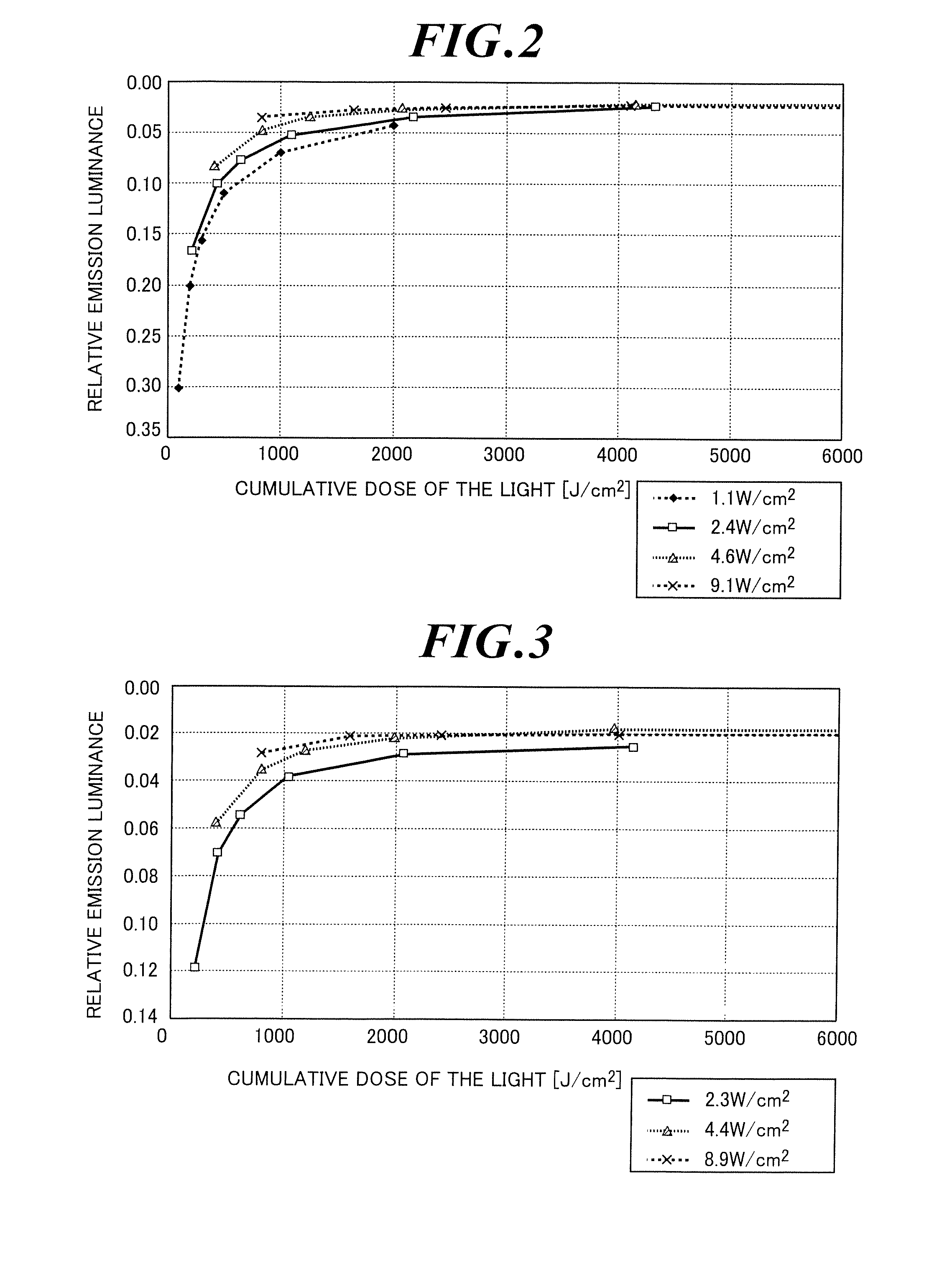
[0032]In the method according to one or more embodiments of the invention, an emission pattern is formed under control of at least one of the light intensity and exposure time as variable factors during light irradiation on the basis of reciprocity failure characteristics involving the modification of the function of an organic functional layer due to light irradiation.

[0033]According to one or more embodiments of the invention, an emission pattern may be formed under control of at least one of the light intensity and exposure time on the basis of reciprocity failure characteristics determined through preliminary measurements of the mutual relationship between the modified level of the function of the organic functional layer due to light irradiation and the at least one of light intensity and exposure time. Through such a process, the light intensity and exposure time can be appropriately determined in accordance with predetermined emission luminance levels so as to form a precise ...


PUM


Abstract

A method includes forming an emission pattern on an organic electroluminescent element including an organic functional layer between two electrodes by light irradiation to the organic electroluminescent element, and controlling at least one of light intensity and exposure time as variable factors during the light irradiation based on reciprocity failure characteristics involving modification of a function of the organic functional layer due to the light irradiation.

Description

TECHNICAL FIELD[0001]One or more embodiments of the invention relate to a method of patterning an organic electroluminescent element. In particular, one or more embodiments of the invention relate to a method of pattering an organic electroluminescent element that can form a precise emission pattern having a predetermined gradation of emission luminance levels.BACKGROUND ART[0002]Organic luminescent elements have been drawing attention as thin luminescent materials.[0003]Organic luminescent elements containing organic electroluminescent (EL) materials (hereinafter, also referred to as “organic EL elements”) are thin perfect solid-state elements that can radiate light in response to a low voltage of several to several tens of volts and have many advantages such as high luminance, high luminescent efficiency, small thickness, and small weight. Such organic EL elements have drawn attention as backlights in various displays, display boards of notices and emergency lights, and surface-em...

Claims


Application Information

Patent Timeline
Patent Type & Authority Patents(United States)
IPC IPC(8): H01L51/00H01L51/56H01L51/50H05B33/10
CPCH01L51/0031H01L51/0014H01L51/0015H01L51/56H01L51/00H01L51/50H01L51/504H05B33/10H10K71/20H10K71/70H10K50/00H10K71/00H10K71/211H10K50/13H10K99/00
Inventor MORIKAWA, MASAHIROSHINDO, HIROYUKI
Owner MERCK PATENT GMBH
Why Eureka
Try Eureka