Photoprinter

a photoprinter and photo printing technology, applied in the field of photoprinters, can solve the problems of time-consuming and costly for users to have to avail themselves to such image photographing devices, and no photoprinters that allow users to easily access

a photoprinter and photo printing technology, applied in the field of photoprinters, can solve the problems of time-consuming and costly for users to have to avail themselves to such image photographing devices, and no photoprinters that allow users to easily access

US20060171004A1Inactive Publication Date: 2006-08-03FUNAI ELECTRIC CO LTD

Image

  • Photoprinter
  • Photoprinter
  • Photoprinter

Examples


second embodiment

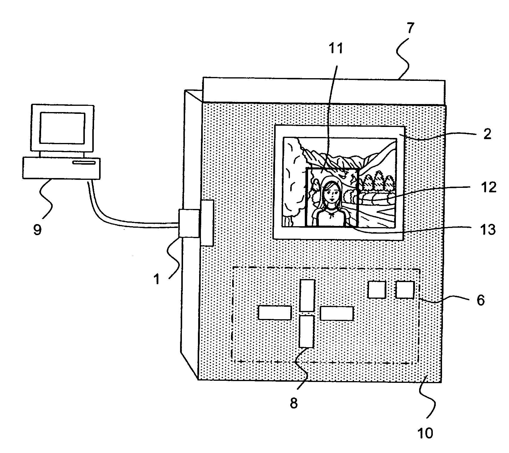
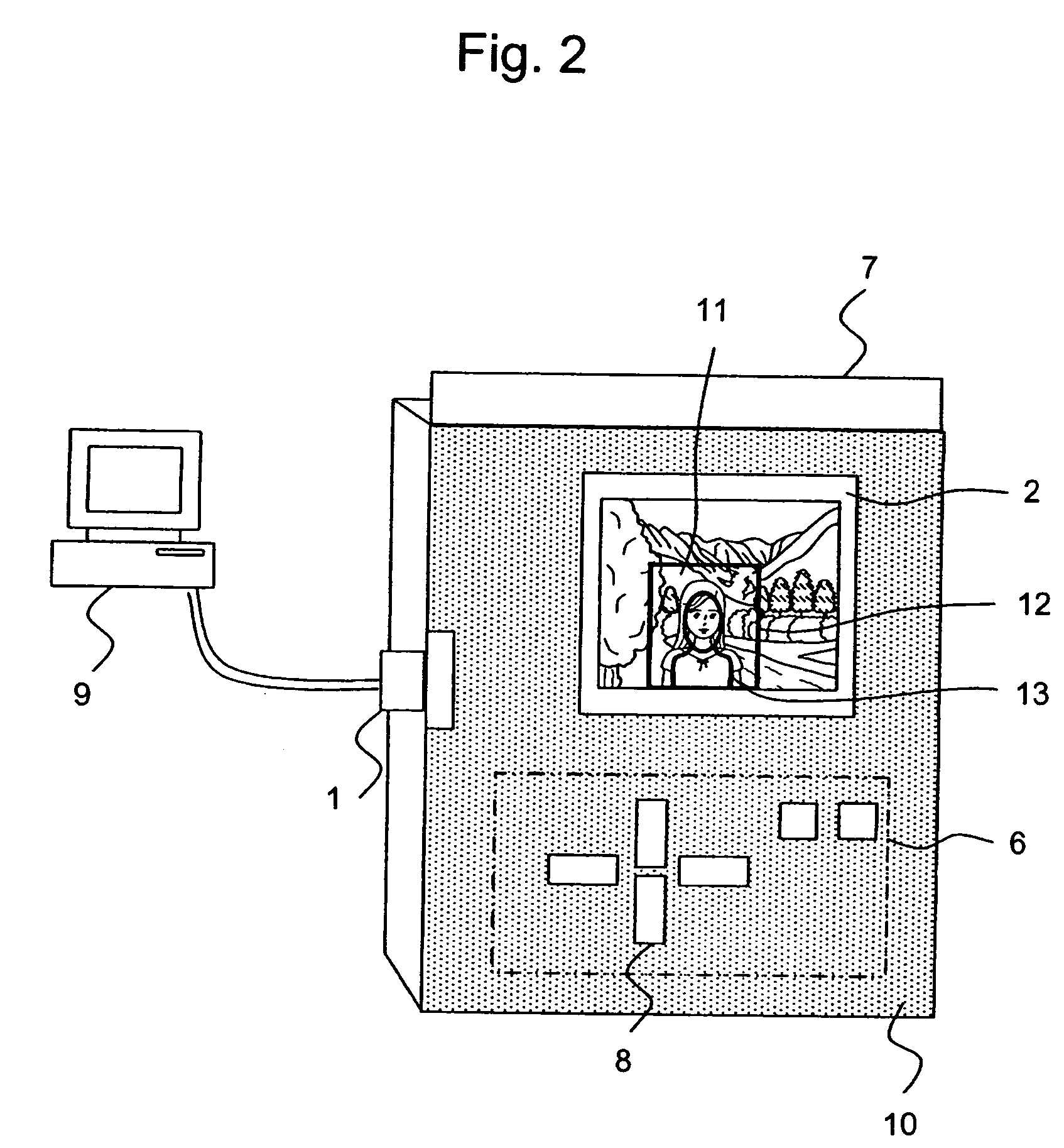
[0064] Referring now to FIGS. 8-9, a photoprinter in accordance with a second embodiment will now be explained. In view of the similarity between the first and second embodiments, the parts of the second embodiment that are identical to the parts of the first embodiment will be given the same reference numerals as those of the first embodiment. Moreover, the descriptions of the parts of the second embodiment that are identical to the parts of the first embodiment may be omitted for the sake of brevity.

[0065] The second embodiment is different from the first embodiment in that that the position and the size of the template are adjusted automatically instead of manually by the user as in the first embodiment.

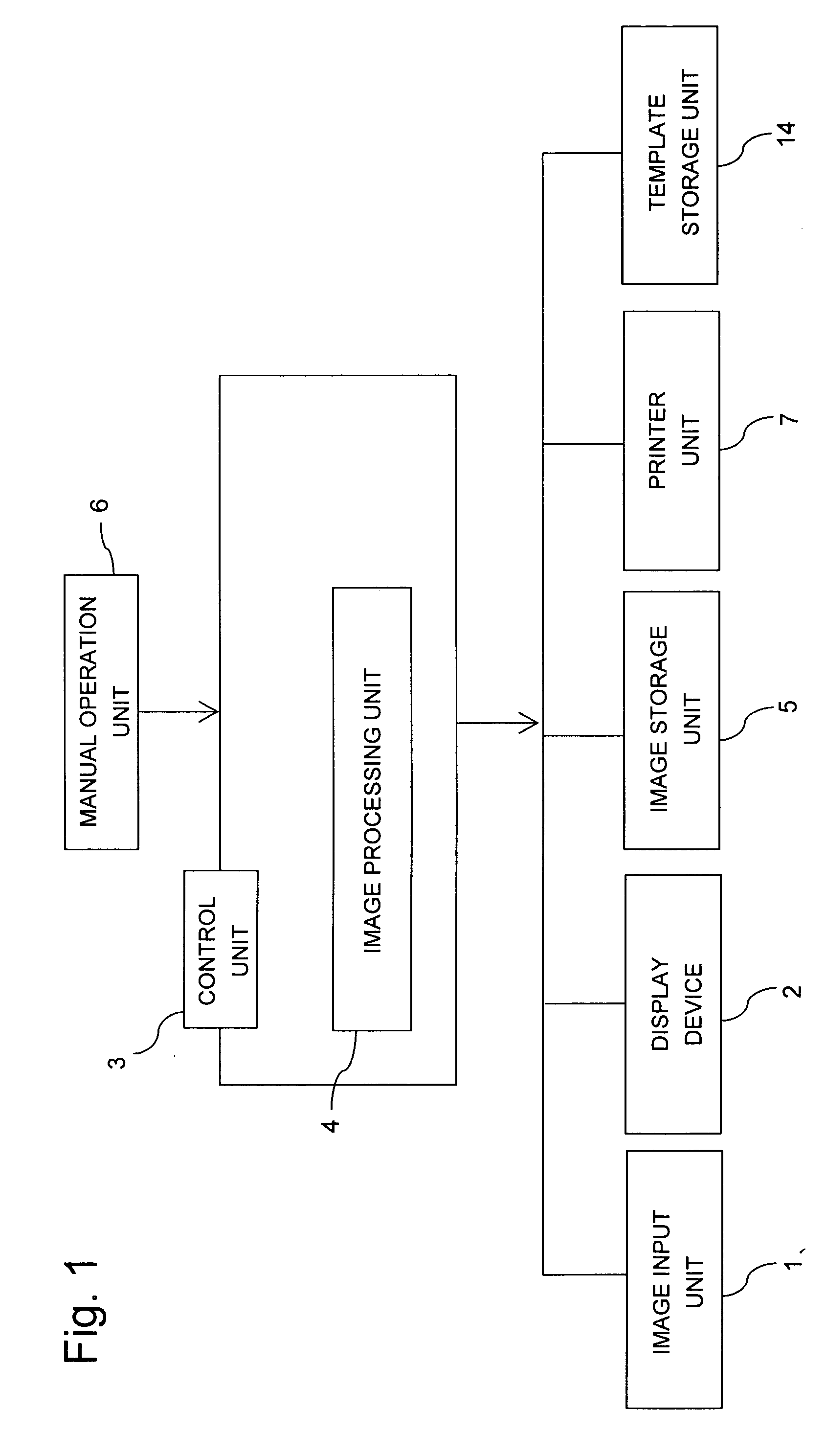
[0066]FIG. 8 is a block diagram of the internal components of a second embodiment. The control unit 50 of the second embodiment is similar to the control unit 3 of the first embodiment, except that the control unit 50 further includes a face image extracting unit 51, an automati...


PUM


Abstract

A photoprinter includes an image input unit through which an original image is configured to be inputted; a display unit configured to display an image; a printing unit configured to print the image displayed on the display unit; an operation input unit adapted to receive an instruction from a user; a template storage unit configured to store a template including an outer guide and an inner guide; and a control unit operatively connected to the image input unit, the display unit, the printing unit, the operation input unit, and the template storage unit. The control unit is configured to create a template-treated image from the original image by displaying a template over the original image on the display unit, and trimming an area of the original image outside the outer guide of the template and performing segmentation around the inner guide.

Description

CROSS-REFERENCE TO RELATED APPLICATIONS [0001] This application claims priority to Japanese Patent Application No. 2005-025949. The entire disclosure of Japanese Patent Application No. 2005-025949 is hereby incorporated herein by reference. BACKGROUND OF THE INVENTION [0002] 1. Field of the Invention [0003] The present invention generally relates to a photoprinter. More specifically, the present invention relates to a photoprinter capable of creating identification photographs such as passport photographs. [0004] 2. Background Information [0005] The idea of employing image processing in devices that are specifically designed to take identification photographs has already been proposed. [0006] Although the increased popularity of digital cameras and photoprinters allows people to take photographs at home with relative ease, people who need identification photographs still need to use image photographing devices specifically designed to take identification photographs like those descr...

Claims


Application Information

Patent Timeline
03 Aug 2006
Publication
US20060171004A1
IPC
H04N1/46
CPC
H04N1/3875
Inventors
HORI, TAKESHI