Method to control spiral start point during ammonite servo track writer process using reference servo track band

a technology of ammonite servo track and spiral start point, which is applied in the direction of data recording, magnetic recording, instruments, etc., can solve the problems of reducing the density and reducing the performance of the driv

Inactive Publication Date: 2006-08-03
SAMSUNG ELECTRONICS CO LTD
View PDF7 Cites 18 Cited by
  • Summary
  • Abstract
  • Description
  • Claims
  • Application Information

AI Technical Summary

Problems solved by technology

Inaccurate servo can lower the density a

Method used


Image

  • Method to control spiral start point during ammonite servo track writer process using reference servo track band
  • Method to control spiral start point during ammonite servo track writer process using reference servo track band
  • Method to control spiral start point during ammonite servo track writer process using reference servo track band

Examples


Embodiment Construction

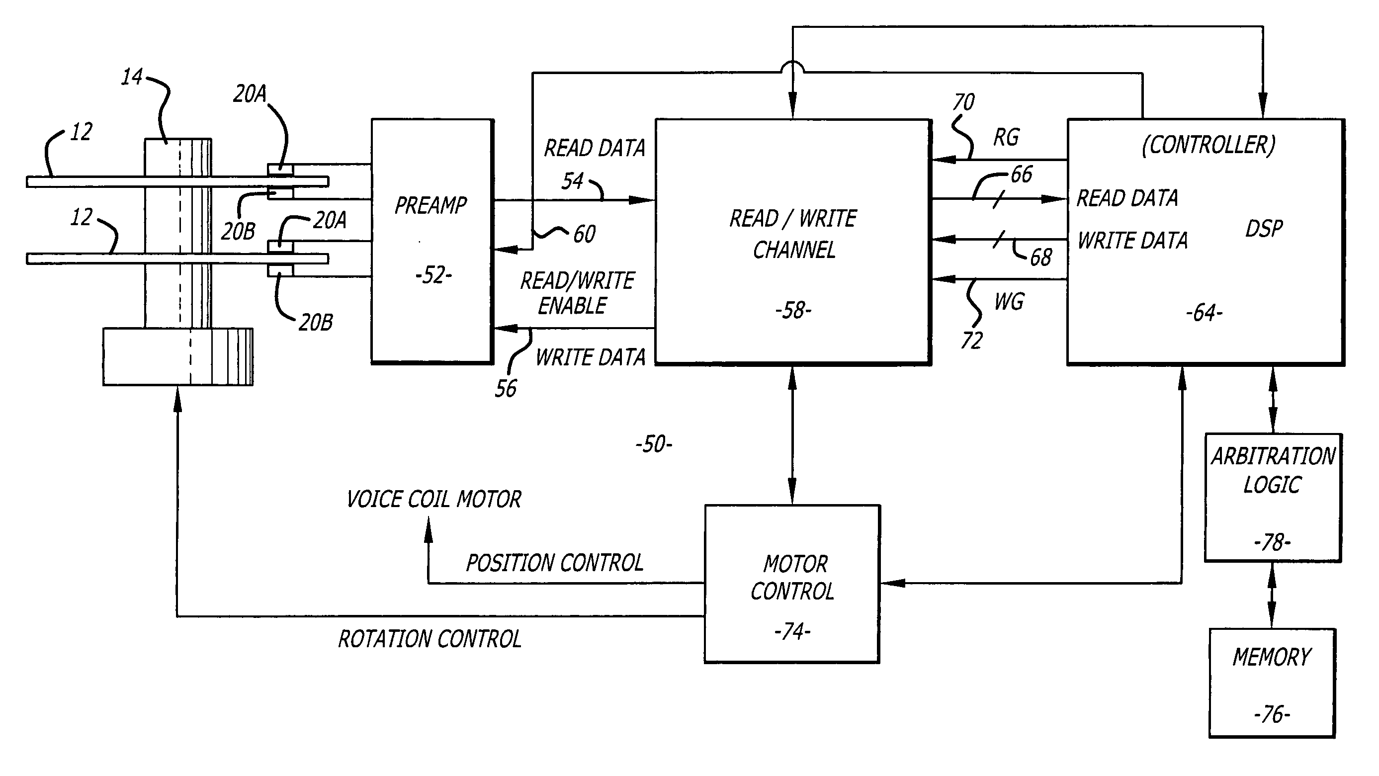
[0020] Disclosed is a method for writing servo information onto a disk of a hard disk drive with a servo writer. The method includes writing a reference servo pattern onto a track of a disk. A head is then positioned relative to the reference servo pattern and a spiral servo track is written onto the disk. The process of positioning the head relative to the reference servo pattern and writing a spiral servo track can be repeated to create a plurality of spiral servo tracks on the disk. The spiral tracks are used to write radial servo patterns that are utilized during normal operation of the drive. The reference servo pattern allows each spiral track to start at a point with the same radial distance from the center of the disk. This improves the accuracy of the spiral tracks and the resultant final servo patterns.

[0021] Referring to the drawings more particularly by reference numbers, FIG. 3 shows an embodiment of a hard disk drive 10 of the present invention. The disk drive 10 may ...


PUM


Abstract

a method for writing servo information onto a disk of a hard disk drive with a servo writer. The method includes writing a reference servo pattern onto a track of a disk. A head is then positioned relative to the reference servo pattern and a spiral servo track is written onto the disk. The process of positioning the head relative to the reference servo pattern and writing a spiral servo track can be repeated to create a plurality of spiral servo tracks on the disk. The spiral tracks are used to write radial servo patterns that are utilized during normal operation of the drive. The reference servo pattern allows each spiral track to start at a point with the same radial distance from the center of the disk. This improves the accuracy of the spiral tracks and the resultant final servo patterns.

Description

BACKGROUND OF THE INVENTION [0001] 1. Field of the Invention [0002] The present invention relates to a method for writing servo onto disks of a hard disk drive. [0003] 2. Background Information [0004] Hard disk drives contain a plurality of magnetic heads that are coupled to rotating disks. The heads write and read information by magnetizing and sensing the magnetic fields of the disk surfaces. Each head is attached to a flexure arm to create a subassembly commonly referred to as a head gimbal assembly (“HGA”). The HGA's are suspended from an actuator arm. The actuator arm has a voice coil motor that can move the heads across the surfaces of the disks. [0005] Information is typically stored in radial tracks that extend across the surface of each disk. Each track is typically divided into a number of segments or sectors. The voice coil motor and actuator arm can move the heads to different tracks of the disks. [0006]FIG. 1 shows a typical track that has a number of fields associated ...

Claims


Application Information

Patent Timeline
IPC IPC(8): G11B21/02
CPCG11B5/59633G11B5/59661
Inventor CHAN, KWONG-TATGAMI, BIPINCHANDRA V.IVANOV, NIKOLAY
Owner SAMSUNG ELECTRONICS CO LTD
Why Eureka
Try Eureka