Inkjet head

a technology of inkjet head and inkjet printing, which is applied in the direction of inkjet machines, printing, and positive displacement liquid engines, etc., and can solve the problem of other limitations of the related ar

Active Publication Date: 2006-08-03
BROTHER KOGYO KK
View PDF6 Cites 2 Cited by
  • Summary
  • Abstract
  • Description
  • Claims
  • Application Information

AI Technical Summary

Benefits of technology

[0013] The second electrode of the actuator unit and the metal portion of the flow-path unit are electrically connected with each other, and the metal portion of the flow-path unit and the metal portion of the reservoir unit are electrically connected with each other through the conductive member. Therefore, in the case where the an insulating material layer is interposed between the metal portion of t

Problems solved by technology

Other limitations of the related art will become apparent to those skilled

Method used


Image

  • Inkjet head
  • Inkjet head
  • Inkjet head

Examples


embodiment 4

[0076] 3] As shown in FIGS. 16 and 18 (modified embodiment 4), an actuator unit 21D may be provided with a plurality of stacked piezoelectric sheets 41D, 42D, 43D and 44D, and individual electrodes 35D and common electrodes 34D, which are alternately formed on those piezoelectric sheets 41D to 44D to sandwich the piezoelectric sheets therebetween. The individual electrodes 35D are arranged, like the individual electrodes 35 of the embodiment described above (see FIG. 9), at positions opposite to the pressure chambers 10. As shown in FIG. 18, through holes 168D are formed to pass through the piezoelectric sheets 41D, 42D and the common electrode 34D and are filled with a conductive material. The conductive material filled in one through hole 168D electrically connects corresponding one of the upper individual electrodes 35D and corresponding one of the lower individual electrodes 35D. Moreover, the common electrodes 34D are connected with each other through a conductive material 68D ...

embodiment 5

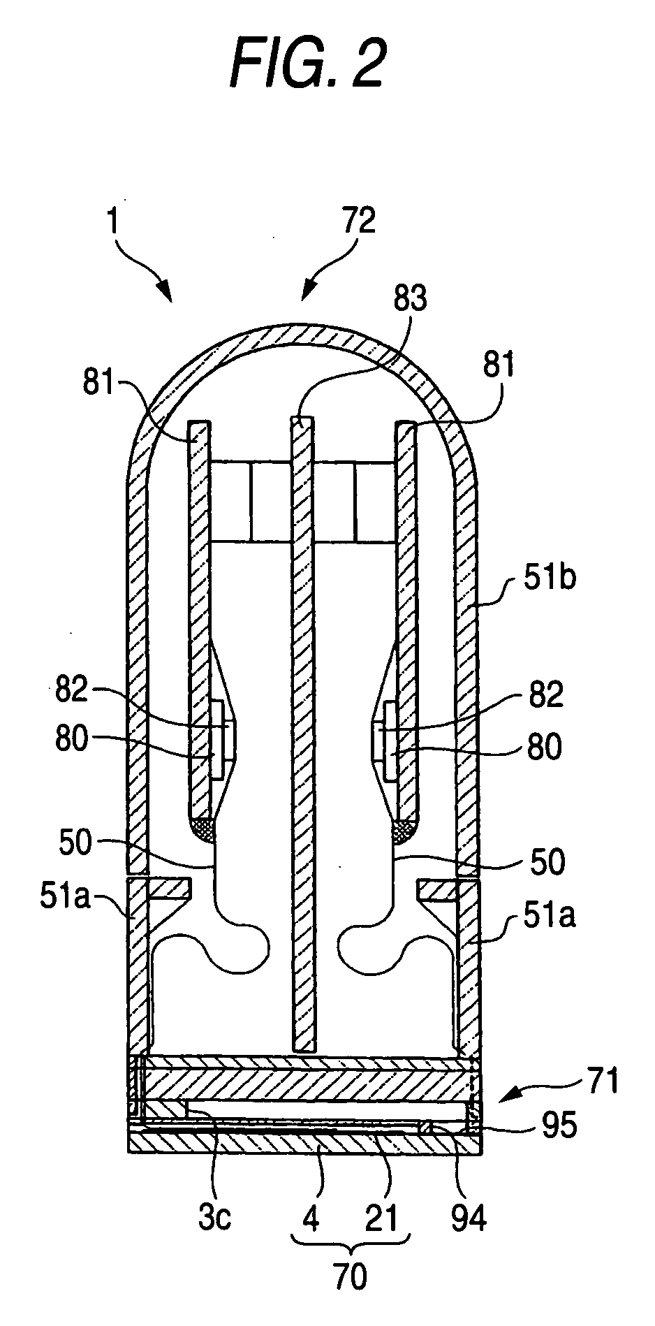
[0077] 4] The flow-path unit and the reservoir unit may be electrically connected by the conductive members, which are individually fixed onto the flow-path unit and reservoir unit (modified embodiment 5). As shown in FIG. 17, for example, a flow-path unit 4E and the reservoir unit 71 may be connected through a conductive screw 98E, which is fixed to a cavity plate 22E and a base plate 23E of the flow-path unit 4E and to the five reservoir plates 60 to 64 of the reservoir unit 71. In this case, the flow-path unit 4E and the reservoir unit 71 are reliably electrically connected with each other through the screw 98E. Therefore, the common electrode 34 of the actuator units 21 is electrically connected with the reservoir unit 71 through the flow-path unit 4E, and the common electrode 34 is reliably kept at the ground potential. Here in FIG. 17, wire 99 for electrically connecting the reservoir unit 71 and the sub-substrates 81 is fixed onto the reservoir unit 71 by the screw 98E. It is...


PUM


Abstract

An inkjet head includes a flow-path unit, a reservoir unit and an actuator unit. The flow-path unit includes a common ink chamber and plural individual ink flow paths. The actuator unit includes plural first electrodes and a second electrode. The first electrodes are arranged to correspond to pressure chambers, respectively. The first electrodes are fed selectively with respective drive voltages for varying a volume of the pressure chambers. One of the flow-path unit and the reservoir unit includes a first metal portion, and the other includes a second metal portion. The metal portion of the flow-path unit and the second electrode are electrically connected with each other. The first metal portion and the second metal portion are jointed to each other through an insulating material layer. An electric connection portion, which is in direct contact with the second metal portion, is integrated with the first metal portion.

Description

[0001] This application is based upon and claims the benefit of priority from Japanese Patent Application No. 2005-7628 filed on Jan. 14, 2005; the entire contents of which are incorporated herein by reference. BACKGROUND OF THE INVENTION [0002] 1. Field of the Invention [0003] The invention relates to an inkjet head for ejecting ink to a recording medium. [0004] 2. Description of the Related Art [0005] U.S. 2005 / 0073562 discloses an inkjet head for ejecting ink from nozzles to a recording medium such as recording paper. This inkjet head includes: a flow-path unit formed with an ink flow path including the nozzles; a reservoir unit for reserving the ink to be fed to the flow-path unit; and an actuator units for applying an ejection energy to the ink in the flow-path unit. The flow-path unit and the reservoir unit have structures in each of which a plurality of metal plates are stacked. The reservoir unit is so jointed to the flow-path unit that its internal flow path communicates wi...

Claims


Application Information

Patent Timeline
IPC IPC(8): F04B43/00
CPCB41J2/14209B41J2002/14217B41J2002/14225B41J2002/14306B41J2002/14362B41J2002/14419B41J2002/14459B41J2002/14491B41J2202/20F04B43/046
Inventor CHIKAMOTO, TADANOBUHIROTA, ATSUSHI
Owner BROTHER KOGYO KK
Why Eureka
Try Eureka