Electrical connector

Inactive Publication Date: 2007-06-05
LOTES
View PDF3 Cites 2 Cited by
  • Summary
  • Abstract
  • Description
  • Claims
  • Application Information

AI Technical Summary

Benefits of technology

[0005]One particular aspect of the present invention is to provide an electrical connector. This invention

Problems solved by technology

However, the shape of the conducting pin is complex.
It is difficult to manufacture and expensive.
Because the force is large when the electrical connector is connected with the electronic element, it is easily deformed after the conducting pins are pressed several times. Furthermore, because

Method used


Image

  • Electrical connector
  • Electrical connector
  • Electrical connector

Examples


Example

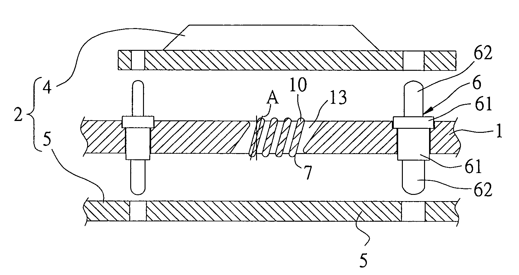
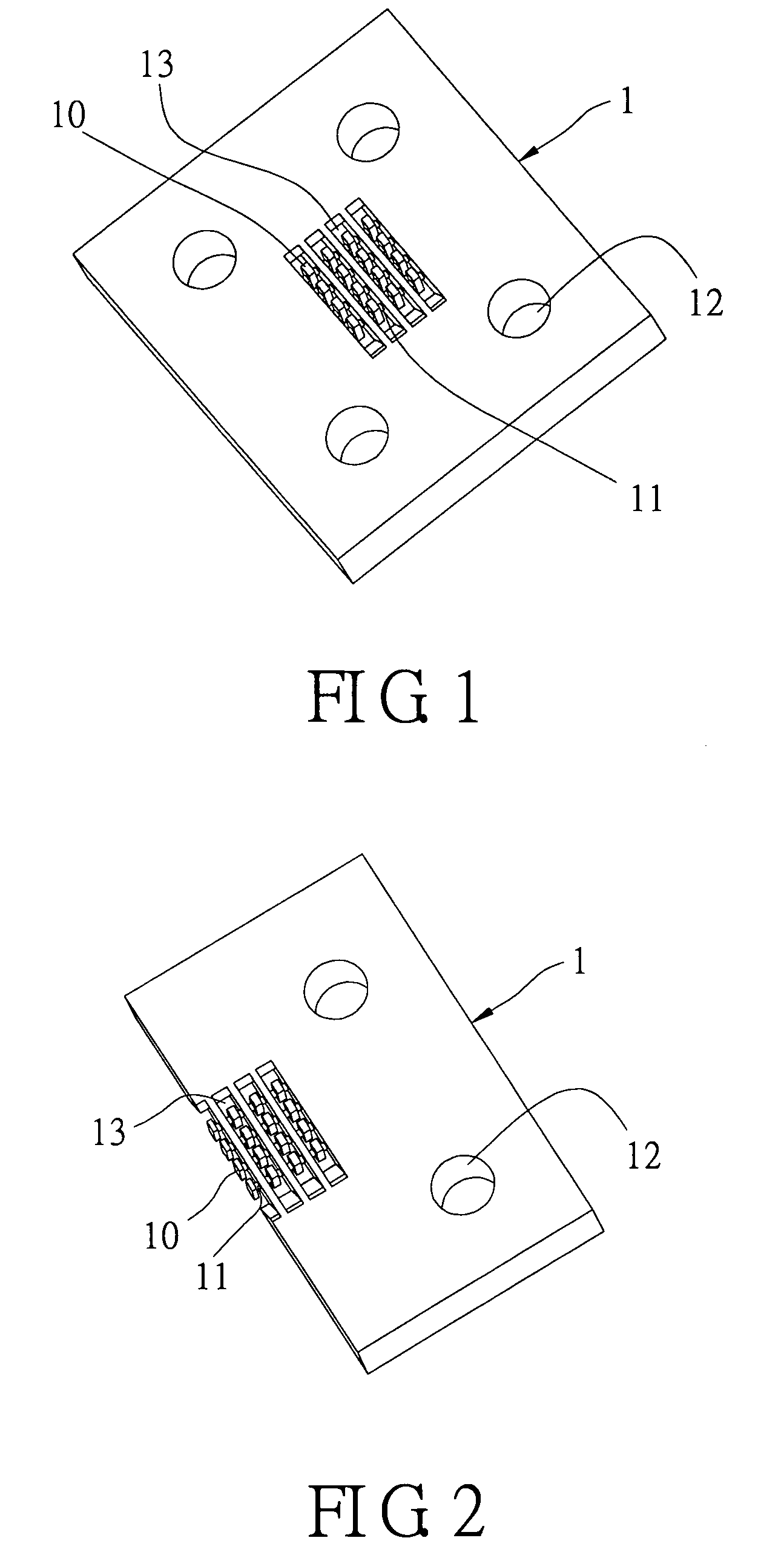
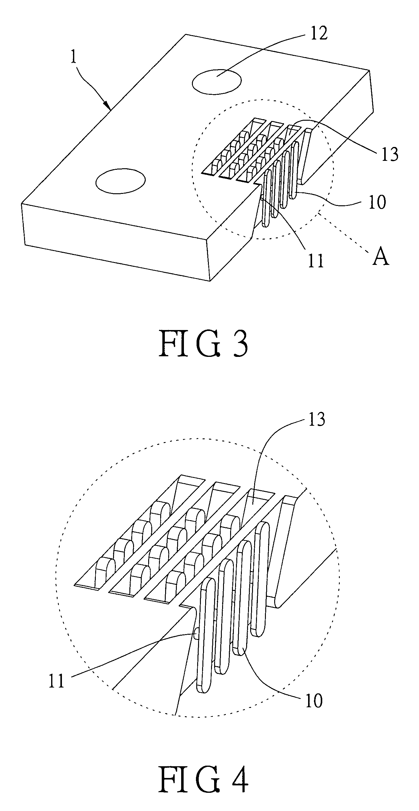
[0018]Reference is made to FIGS. 1˜5, which show schematic diagrams of the electronic connector of the present invention. The electrical connector includes an insulating body 1 having a receiving space 13, a butting electronic element 2, and a swinging body 10. The swinging body 10 is located in the receiving space 13 and swingingly contacts the butting electronic element 2. In this embodiment, a chip module 4 contacts a butting electrical board 5. The swinging body 10 has a conducting material. The conducting material is a conducting layer 7. The conducting layer 7 is formed on the swinging body 10 via a physical film plating method (such as sputter plating, or evaporation plating). The insulating body 1 further includes a connecting part 11. The swinging body 10 is connected with the insulating body via the connecting part 11. There are contacting points located at two sides of the swinging body 10. The line A linked between the two contacting points is inclined to the surface of ...


PUM


Abstract

An electrical connector includes an insulating body having a receiving space, a butting electronic element, and a swinging body. The swinging body is located in the receiving space and swingingly contacts the butting electronic element. The swinging body has a conducting material. The structure of the electrical connector is simple and easily manufactured. This invention makes the electrical connector contact the electronic element well and reduces the cost of manufacture.

Description

BACKGROUND OF THE INVENTION[0001]1. Field of the Invention[0002]The present invention relates to an electrical connector. In particular, this invention relates to an electrical connector that ensures a firm contact with an electronic element and reduces manufacturing costs.[0003]2. Description of the Related Art[0004]Electrical connectors of the prior art usually include an insulating body, and conducting pins received in the insulating body. The insulating body is comprised of pin receiving slots and the conducting pins are received in the pin receiving slots. The conducting pin includes a fixing part and a contacting part located at the two ends of the conducting pin. The electronic element is pressed to electrically contact the conducting pins of the electrical connector. However, the shape of the conducting pin is complex. It is difficult to manufacture and expensive. Because the force is large when the electrical connector is connected with the electronic element, it is easily ...

Claims


Application Information

Patent Timeline
IPC IPC(8): H01R12/00
CPCH01R13/035H01R13/6315H01R23/68H01R12/7052
Inventor JU, TED
Owner LOTES
Why Eureka
Try Eureka